, '.
I'
..
Page 13'
, "
"\
.
Table
2~
.Performance
Chec'k
Procfedure
(2
of
3)
I
;/
) .
'.
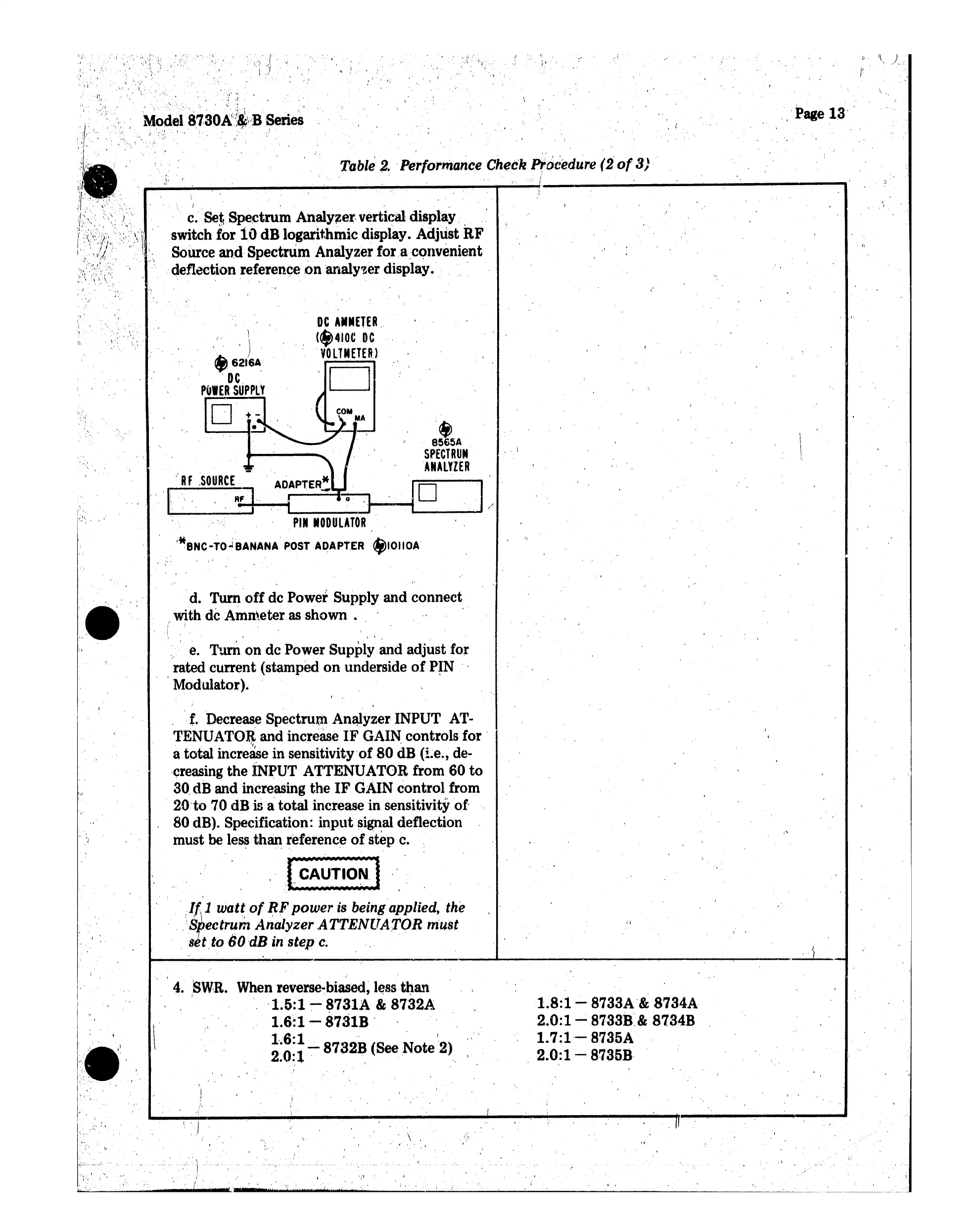
c.
Set
Spectrum
Analy~e~.
vertical display
switch
for 10dB logarithmic display. Adjust
RF
Source and Spectrum Analyzer
foraconvenient
deflection reference onanalyser display.
"..' ,
,,'
.
i •
'.
•
,,'
".'
-J
Model·
8730~":~\':B··Series
,
..,
I',.
,
',';
I;
i,
,',
:.\
.'.
\
-'.
e!5A
SPECTRUM
ANALYZER
o
DC
A.METER,
(*410CDC
.
VOLTMETER)
(.
\
,.
')
f)62t'6A.
.
DC
PulER
S,UPPLY
D
. "
.d. Turn'
off
de Power Supply and connect
with de Ammeter as shown .
;' i '
I "
I I ' .. '
\.
j , ,
" e. Turn on dc Power Supply and adjust for
rated current (stamped
on
underside
of
PIN "
,Modulator). '
,
~,.
I\RFSOURCE~ATPTER~
~~.
I
....
O
__
.I.
"
PIN
MODULATOR
.
.
'*8NC-TO~8ANANA
POST
ADAPT.ER
*IOIIOA
-,
"
, .'
. ",
" ,
-
.,W'
, .
'.J
, '.
,
,t.
Decrease Spectrum Analyzer INPUT AT
..
TENUATOR and increase
IF
GAIN controls
for'
a total increase in sensitivityof 80
aa
(i.e., de-
.creasing the
INPUT ATTENUATOR from 60
to
30.
dB and increasing the
IF
GAIN control from
20'to 70 dB is atotal increase in sensitivity
of-
80 dB). Specification:
input
signal deflection
must
beless than reference
of
step c.
f
\
'
...
~",
·
!~~
1
w.
at~
of
J:lF.
power is
being
applied.
the
..
,:Srectrum Analyzer
,A
TTENUATOR must
·
setto
60
dB
in step
c.
.,'
.. .
I
t
, , ' .
1.8:1-
8733A'& 8734A
2.0:1
~
8733i:f& 8734B
1.7:1''-
8735A
.
2.0:1-
8735B,
, '
\,
,
When reverse-biased, less
than
'1.5:1
-.
~731A
&8732A
1.6:1 - 8731B '
~:~;~
-
8732B
(See
Note
'2)
, \
':1
r.'
I : I
·
"\
.
,.
, i
$
, '
4.SW,R.
)
,',
..
'.
i·
 Loading...