0\
:Pag(,5
.,.
. ..
~~
..
~
"'..
,.-.,~.,
..
~
--..
~.-
,
r-
.•...••.
~
h~_··
.."_..
·'M
__
··
~
__
_.
__
,
" , I,
~
.'
" .
"'.
, ,
I.
"!)
i
_..
-,._-~-
..
_---
._.-,,~-_..:..~-l\----
-"---"--'--'-
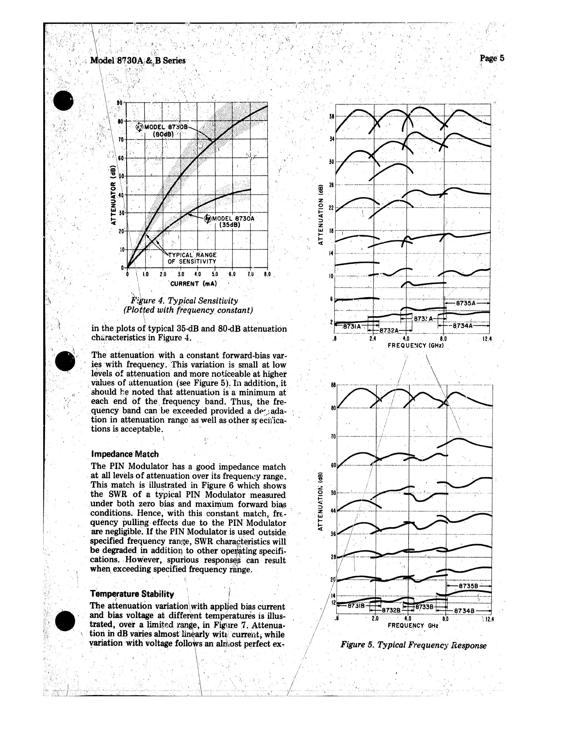
Figure,5
..
Typical Frequency Response
'\
.
70
..
_--
..
_
....
_
......
_
....
--
..
1-·
..;·..·
......
_-··
..··.. ·1
, '. " ,
__
,
_._~
.. _ ...n,
__
~
...
~M-
_'
__
'"(';"
._
10,:··
..
···
..
,·
..
;,..-
..·.:···,
" \'
.8
:,'
14
...
z
o
22
~
':>
z
w
18
.....
....
et
i
-
'.'
./
I
I
..':
;i
.
I " .,
..
,
("'!
,
,.;.1
",
" :
I ,
/
I
,/1
.
I,'
1;'.1
-r.
"
.',
'
,f
~
, ,
,
.
v-.
I·'
•
".1"
,,'
"J'
':
.,11 . ,,'
./
'..
. "
"I !l
7.0. 8.0,
..
~,
'.'
,;
,
'6.0
.,'
. ./
','"
.
\"
,
~I
:f,'
-j"
i,'
II~"
'I,
"I
..
".:,
,".
o ,
, I
\
.
1.0
2.0
3.0
4.0
\ . 'CURRENT (mA) .
.il/kure 4. Typical Sensitivity .
(Plotted with frequency constant)
I
\
'.'
. . .
~
in
the
plots
of
typical 35·dB
and
BO-dB
attenuation
chsracteristicsin
Figure 4. "
i
\'
'.
The
attenuation
with a
constant
forward-bias var-
ieswith
frequency. 'This variation is small
at
low
\.
,
.',
. .
levels
of
attenuation
and more noticeable'at higher
.values
of
attenuation
(see Figure 5).
In
addition.Jt
'should
be
noted
that
attenuation
is.'
a minimum
at
. each
end
bf
the'frequency
band.
Thus,
the
fre-
.quency band
canbe
exceeded provided a
dp~)a.da·
tion
in
attenuation
range as well
as
other
stecif'ica-
tions is acceptable. ,
\
i'
,
.
Impedance
Ma·tch
.
The
PIN Modulator has a good impedance
match
, at. all levels
of
attenuation over Its frequency range.
This match is illustrated in Figure 6 which shows
the
SWR
of
a typical PIN Modulator measured
..
under
both
zero bias' and maximum forward bias
conditions. Hence, with this
constant
match,
fre- .'
quency
pulli~g.
effects due'
to
the
PIN' Modulator
are negligible,
If
the
PIN Modulator is used outside"
specified frequency range,
SWR
chara~t;e.ristics
will
be
degraded in addition
to
other'
'ope~l~ting
specifi-
cations. .However, spurious responses can result
when, exceeding specified frequency
r$l1g
e.
\ .
I I
" .
\
" I
,'1
Temperature Stability
,I
...
.
.:.
I ,
'Ihe attenuation variationiwith applied bias
current
..
and
bias voltage at different temperatures
is'
illus-
.•
'
tt!ate~,
dOBver,~
l,ima1it0d't~anl;:
'e,
lin.
F~tg1·,I~e
,7
~
,Atttenh'~la
\ Ion m .' . vanes mos
•.
In .ar y
~1
~/.
curren ,W. 1e
variation
'\VitI,
voltage follo s an
alri;kost
perfect ex-
'",
"
.1._
..
'\'
,"
" ..
, .
" '
'.'
I
'.
v,
I
, ',,\
.,
'.{
"
",
/.
I
··/·41··
.'
:'\·:·,',
..
.......
'."
.
\',
. "
..
"
".',
' .'
I; ,
\
;~\
.
,
~
; .'
" ,
"
:,
I.
,
, .
/
/
!
I
i"
Ii
.............
., «," ,
\..
...
,
..
I .'\
~DC':l~.;.;.....;,,
...............
:o...-
.......
~..-..:...-.....:.....~
_"
_"'-.L..\-"-'
__
._
......
,~".~~
 Loading...