.1
','
,\
:,~,..
"
,'
,.'
).
'
)'1
I )
,
..
r
..
(I
.
I;'
,I
.',
.;
, \ '. .' \ ,I
'Page
7.
) ,.
'}"\
, "
" .'.
i
~
I'
,
J' I
~
,
.
"oe
'POWER
SUPPLY
~6216A
t,'
"
",:
I
'I
:MODULATED
RF
SIGNAL
;-
;t,·'.··,
"
,
,
.
.
.,
I,',",
'.,
.,
t'
I
, '
,,
:',
'I':
I '
I,'
-;
( .
\
;,
'
,~)
j " ' "
't'
d',' '.' '.1
...
.
~
300.n
,')
,','
,','
, 1
~
"
/"
I,
PIN,·MODULATOR
" "
,I
"
• ,I
'I,
I.,"
,I,., •
., '
,
,
\,,'
"I',
'"
"
.' ,
I
I'"
i:,
, , ,I
,
II'
," "
,,' ":.\
..
' '
"",
*,
MODULAtiON
),)'
SOURCE,
~
.....
UNMODULATED
RF '/"'."'
....
;
\'
SIG'NAL'\<.'
lir-----ti-~
I.
'."
1--_----_
'.
I""
I','
. '
'I'
I
,
1,1
• ,
,/'.
,
quency
rates
always'
produce'
the
best.leveling.
,":.'
However to
determine
whether,
or
not
~riy
system ' " ../,
, , , • I \
is' leveling properly,
an
oscilloscope
and
,~lystal
,'.!.'
detector
should
be
used
at
!~h~
te~e~ed
RF'
output,
, '
"
" I,' ,
'~
.. "
\
"
"\'
" 1
"
" ':,
::'~ ~
, I J ' "
;1.,
~I)'
l ' ' "
I"
\'. ' ,
I ',' t
',",
'.
I'·'
'.
I,
.)
,
'\,
'i'
I,.,
,
,"
'
,
,.',"
l'"
','
't"''''
:"1' ,
..
-.....
, ,
,,1\
I,
'I'",'"
,.
i'l
LEVELED'
"
AF
,POWER,
7'
<,'
"
, I
.'
,. "
"
"
,>,
~
I ,) " '
i "
, '
I
,
LEVELE,O
"'RF
POWER
----
'
,
,.
'I
/
If
l
'
, :,'
,,'
>
,1,1
POWER
,METER
$432A,
DET'ECTING
,
D,~VICE
..
'.
...u.--........,
I,
.
~'\
, ,
RECORDER
OUTPuT
"',,
'-
.
,'\
I: )
''i'
',?'
0,
81AS
o @
"".'"
'/
20KO:HM
'
.'.
RESIS'rOR
"',
'
LEVELER
.
'"
'I
AMPLIFIER.
~
HOI-,84MA
'.'
" ,
',.,
,-,
;,1
1
'UNLEVELED
RF
.,
POWER
,:'
',
\ .
,
'I'
,
, '
I I
:,
"
""It
'.:.,(:'
.::',:
.
•'
I,
.
DIBECTlONAl
.)""""';",.,'.,,.',"
, ,
"i.
COUPLER
'
':'.,
,.<~7,9~n:,
J "
~FOR'
.P~CSE
MOOULATION:
~MODEL.~
~I~A,'
t'.'
"
"..'
,)
,,"";
",'
".
;'
,.'
",'.
:';'
\
I:'
':"':;:':
FOR
A~~LITtJ)DE.
'~1ODUb,~r.I()N:'\t)M9~EL6!5IB
,
Pigure'
9.
'.,Typical
Clqsed
L~)'op
t~veling
S;istem',
.,'
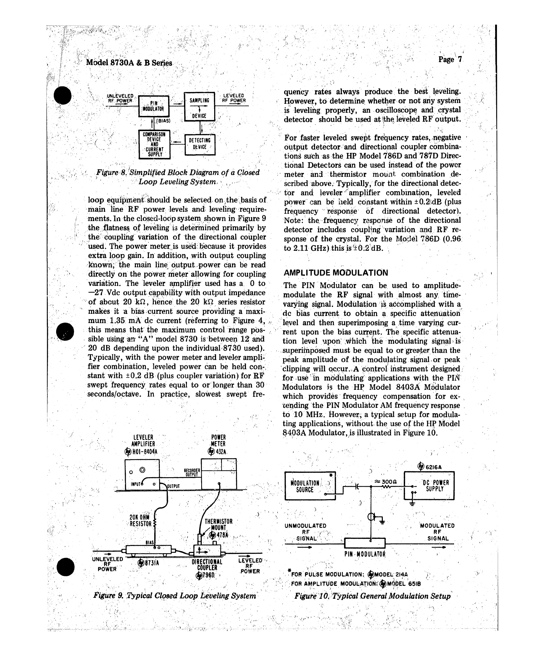
Figutlj"l O)Typical,Genera/Modulation
~etup
, ' .. : ' , " " I,
'~
) ,
~\
,
,
"."',,
,
I,,"
"~'I
,
,,"I
I
I".'
"
"',
'.i
I'
/,
Fig~re,8.
!Sim,plified
Block
Diagram
of
a
Glosed
.)
, .
','"
, , .
,
'"
i.Loop. Leveling System,',
It'
.,"'~
,~"''.
'::~
"\
I',:,' I.
,','
..
',',:"
..
'
.: ,
,.,
'"
1\;,1" '
,,.
I '
, ,
" "
:
""I'
'"
I
,i I
~
, "
""
I .
1''''
.:
"I,
( .
/'
,
-1
'I :,"
:' I"
'l,'
i
J
, . ,
" ,J I" ?:
...
;.
For'faste~
leveled swept frequency rates,
l~~gative
, output detector-and directional couplercombina-
tions
such
'as .the HP Model 7'86D
and
78·7D Direc-
. tional
Detectors
can
be
used insteadof
the
power
.:
meter'
and ,"thermistor
mount
combination
.de-,
scribedabove.'Typically,'
for
the
directional detec-
,
'.,i'
tor
and. leveler campJifier combination, leveled
,
loop
equip~nen(should
be selected.
onthebasis
of. ' power can be
held
constant
within ±0.2'idB (plus
.main "line
R.F·
power. .levels and' leveling: .require-
fr~quency
'.'
response
hf
directional detector).
ments.
III
the closed-loop system. shown in-Figure 9 Note:I the,'
f~quency
response
of
the
directional
:the".~atnes~o..~
lev~1iIlg'i3
deteririi'n~d
primarily by
detector
includes coupling
;:variation,a~d,
RF
re-
,,'.:' the,',co.\1plirig' variation
of
the
directional coupler spouse
of
the
crystal.
For
the
~~~~Jel
7,'86D
(0.96.
,,"
:used. l'he
powermeteris
usetr,Q'ecause
it
provides
to
2.11 GHz)
this
,is
I±O,;2"dB.
,,'
".
i ,
extra
190P gain. In' addition,
with
output
coupling
,'l(nQwl\;"'t,he' main
line'.output.power
can
be read
directly
on
the
powermeter allowing
for
coupling'
AMP~ITUDE
MO'DULATI'ON .
'variation.
The
'leveler
~pIU~.er
used
has
a, 0 to,
'The
PIN' Modulator can be, used
to
amplit~de-'
-27,
Vdc
output..c~p~l,)i1ity
WIth
output
impedance modulate
the
RF' signal with
.almost
any
'time-
.""
of
about
20
'kn,
hence'
the
20
k,Q
"series resistor 'varYing signal. Modulation
'~~accompl,ished
with
a"
•
::'"
'i,
makes it 'a
biascurrentsource
providing a
'maxi-dcblas'
'current.
to
obtain
a, specific attenuation
mum, L3S'
rnA'
decurrent
(referring
to
~igltr.e
4,
"1'
"level and
thensuperimposi~ga
.time varying cur-
.-
'.
this means
tha,t'the
maximum control range
po~:
.'
rent upon the bias current,
Th~
specific
attenua~
"
'.
,sible
using 'an'
"A"
model
8730
is' between
l~'and
tion
level
~.tpon~"which
the
'modulating
signal
is
.
..
",
20 dB depending
upon
the
individualB'[Sf) used).. '.
"sllperHnp6$~d'
must
be equal
to
or
'greater..
than
the
Typically, with
the
power
meter
and
leveler
ampli-'
peak
amplitude
of
the,
modulating signal,
or
peak
fier combination,
leveled
power
can be, held con-, ' 'clipping will
QC,<;\1r
."A
'¢ontroi
instrument
designed:
stant with ±0.2 dB,(plus coupler variation) for R'F
fQr,
I
use
'.
'tn
modulating
applications with
~he
PH~"
swept 'frequency rates
equal
to
orlonger
.than
30'
Modulators is
the'
HP Model
8403A
M,odulator
',seconds/o,ctave.
'In
practice, slowest swept' fre- which provides'
frequency
compensation'
for
ex-
..
.'
;'.
tending ·the.PIN Modulator AM frequency response .
. )
':':",
tolD
MHz. However, a typical
setup
for modula- '
J; , , ting applications, without. the use
or
the
HJi'
Model'
~1*P3A
Modulator.Isillustrated in Figure
10.'
" ,
• .
,',
\',
II,'
',I. .r.,
'',i'~:
'~
I ',' I,.:
"It'
j,','
,,'
I
. '
"·.:"··e'"
,(,
.
, '
 Loading...