Security Functions (Continued)
2. As soon as the computer is turned on, press and hold F10 until you enter Computer Setup.
Press Enter to bypass the title screen, if necessary. If you do not press F10
as soon as the computer starts, a restart will be necessary.
3. Select Security, then select Setup Password or Power-On Password and follow the
instructions on the screen.
Before exiting, click File > Save Changes and Exit.
To change a Power-On or Setup password:
1. Turn on or restart the computer. If you are in Windows, click Start > Shut Down >
Restart the Computer. Run Computer Setup (F10).
When the key icon appears, type your current password, a slash (/) or alternate de-
limiter character, your new password, another slash (/) or alternate delimiter character, and your
new password again as shown:
current password/new password/new password.
NOTE: Type the new password carefully since the actual characters do not appear
on the screen.
2. Press the enter key.
The new password will take effect the next time the computer is restarted.
To delete a password using Setup:
1. Turn on or restart the computer. If you are in Windows, click Start > Shut Down >
Restart the Computer. To delete the setup password, run Computer Setup (F10).
2. When the key icon appears, type your current password followed by a slash (/) or
alternate delimiter character as shown. Example: currentpassword/
3. Press the Enter key.
To delete or disable the Power On and Setup passwords:
1. Shut down (Power down) the system and disconnect the power cord from the outlet
or the system unit.
2. Remove the chassis cover.
3. On the system board, remove the jumper on pins 1 and 2 of header E49 and place
only on pin 2.
4. Replace the chassis cover and reconnect the power cord.
NOTE: Setup password may be used in place of Power-on password to boot system.
NOTES:
[1] For more information about Setup Utilities refer to the Computer Setup Guide.
[2] If for any reason the Setup utility is not accessible to unlock the Smart Cover Lock
then a FailSafe key is required to bypass the Smart Cover Lock and open the computer.
Refer to the Hardware Reference Guide on how to use the FailSafe key. To order a Fail-
Safe key contact HP.
[3] Available on some models.
Diagnostic Functions
Diagnostic functions are provided by the Setup Utility (in system ROM) and by Insight Diag-
nostics. Insight Diagnostics provides detailed system information including:
• Processor type and speed
• Memory amount, mapping, and integrity
• Hardware peripheral availability/settings
• Hard drive type, space used/available
• System identification, asset tracking
Insight Diagnostics may be found on the Documentation CD that ships with the computers.
Error Conditions and Messages
NOTE: Power LED blinks are repeated after a 2 second pause until issue is resolved,.
Beeps continue for 5 iterations and then stop.
NOTES: L = long, S = short
Security Features
Feature Purpose
How It Is
Established
Removable Media
Boot Control
Prevents booting from removable media
drives.
Setup Utilities. [1]
Serial, Parallel,
USB, or Infrared
Interface Control
Prevents data transfer through integrated
serial, parallel, USB, or infrared interface.
Setup Utilities. [1]
Power-On
Password
Prevents use of computer until password is
entered. Can apply to both initial startup
and restart.
Setup Utilities. [1]
Setup Password Prevents reconfiguration of computer until
password is entered.
Setup Utilities. [1]
Network Server
Mode
Provides unique security features for
computer used as server.
Setup Utilities. [1]
DriveLock [3] Prevents unauthorized access to data on
drives supporting password protection.
Setup Utilities. [1]
Smart
Cover Lock [2, 3]
Software-controllable solenoid that, when
activated, prevents unauthorized access to
chassis interior.
Setup Utilities. [1]
Smart
Cover Sensor [3]
Indicates computer cover or side panel has
been removed. Can be set to require
password for restart after cover or panel
removal.
Setup Utilities. [1]
Drive Protection
System (DPS
Diagnostic tool built into hard drives on
select models designed to discover
problems that might result in unwarranted
drive replacement.
Setup Utilities or
Diagnostics for
Windows.
Memory Change
Alerts
Detects addition or removal of memory
modules. Notifies system administrator.
Refer to Intelligent
Manageability
Guide.
Ownership Tag Displays ownership information as defined
by system administrator during system
startup. (Protected by setup password).
Setup Utilities. [1]
Kensington
CableLock
Provision
Inhibits access to interior of computer
chassis. Can also be used to secure
computer to a fixed object for prevent theft.
Requires Kensington
cable lock accessory
to secure computer
to a fixed object.
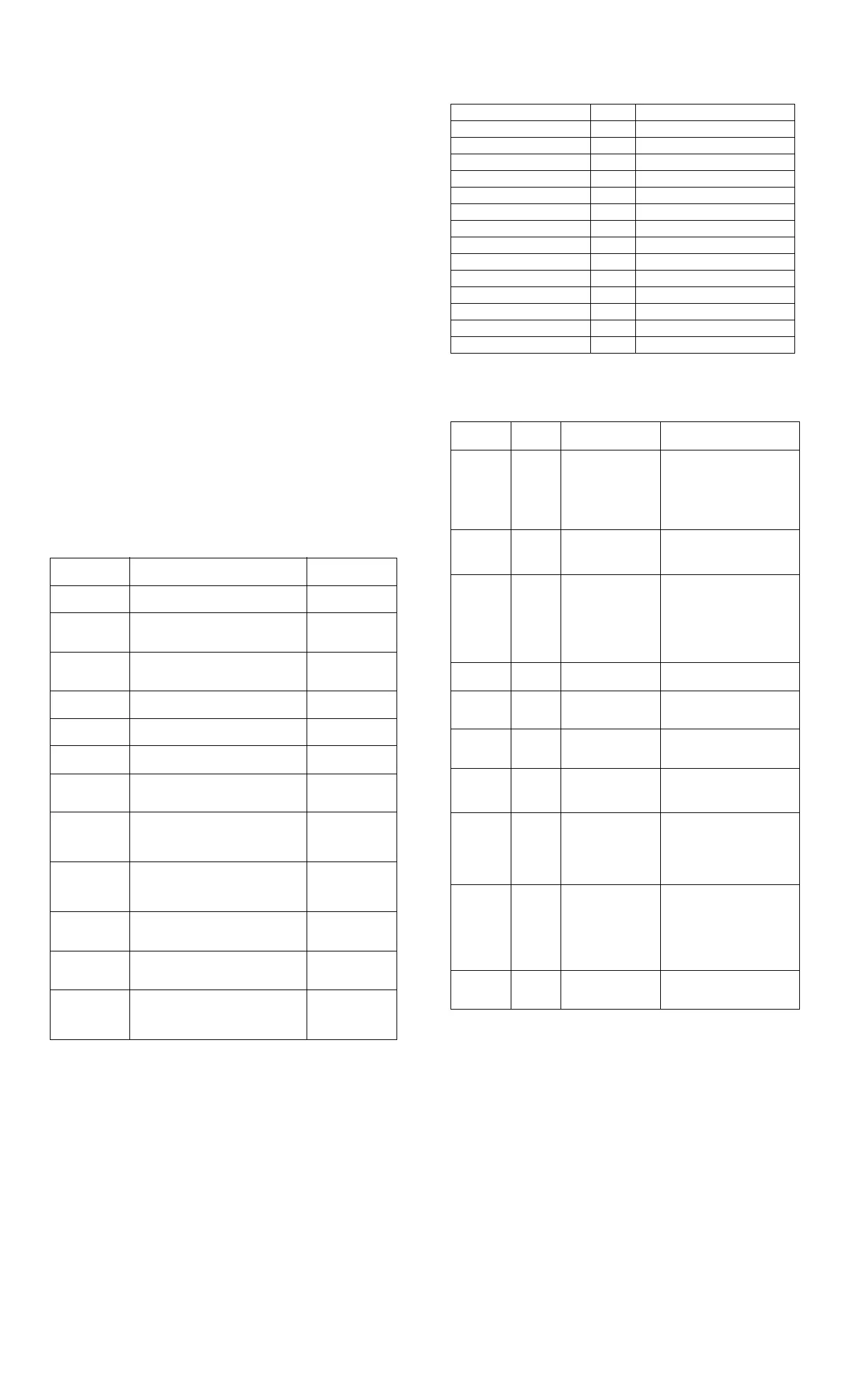
Chassis LED and Beep Messages
Power LED # Beeps Event
Steady green None S0 System on (normal operation)
Blinks green @ 0.5 Hz None S1 Suspend
Blinks green @ 0.5 Hz None S3 Suspend to RAM
Off (clear) None S4 Suspend to disk
Off (clear) None S5 Soft off
Blinks red 2 times @ 1 Hz [1] 2 Processor thermal shutdown
Blinks red 3 times @ 1 Hz [1] 3 Processor not seated / installed
Blinks red 4 times @ 1 Hz [1] 4 Power supply failure
Blinks red 5 times @ 1 Hz [1] 5 Memory error
Blinks red 6 times @ 1 Hz [1] 6 Video error
Blinks red 7 times @ 1 Hz [1] 7 PCA failure
Blinks red 8 times @ 1 Hz [1] 8 Invalid ROM checksum (error)
Blinks red 9 times @ 1 Hz [1] 9 Wrong power supply input voltage
Blinks red 10 times @ 1 Hz [1] 10 Bad option card
Common POST Error Messages
Screen
Message Beeps Probable Cause Recommended Action
101-Option
ROM Error
1L, 1S 1. System ROM
checksum error.
2. Expansion card.
3. CMOS corruption.
4. System board
1. Verify ROM, reflash if
required.
2. Remove suspected expansion
card, reboot.
3. Clear CMOS memory, reboot.
4. Replace system board.
103-System
Board
Failure
none DMA, timers 1. Clear CMOS memory.
2. Remove expansion boards.
3. Replace system board.
164-Memory
Size Error
2S Incorrect memory
configuration.
1. Run Setup (F10).
2. Check DIMMs for proper
seating, proper type, and HP
compatibility.
3. Remove DIMMs singularly
and reboot to isolate faulty
DIMM.
201-Memory
Error
none RAM failure. Same as 164.
214-DIMM
Configura-
tion Warning
none Populated DIMM
configuration is not
optimized.
Rearrange the DIMMs so that
each channel has the same
amount of memory.
301-, 304-
Keyboard
Error
none Keyboard failure. Check keyboard connection or
keys. Replace keyboard. If 304,
possible system board problem
501-Display
Adapter
Failure
1L, 2S Graphics controller. 1. Reseat graphics card.
2. Check monitor connection.
3. Replace graphics card.
1720-
SMART
Hard Drive
Detects
Imminent
Failure
none Hard drive is about to
fail.
Run drive protection system test
if available. Check for firmware
patch for erroneous error
message.
1794-
Inaccessible
devices
attached to
SAATA 1
and/or SATA
3
none A device is attached to
SATA 1 and/or SATA
3.
If using Windows 2000 or
Windows XP, change “SATA
Emulation” to “Separate IDE
Controller” in Computer Setup.
If not using these operating
systems, relocate the devices to
SATA 0 or 1.
1796-SATA
Cabling
Error
none One or more SATA
devices are improperly
attached.
Ensure SATA connections are
used in ascending order starting
with SATA 0.
 Loading...