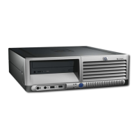
Miscellaneous Parts
1 Heatsink with fan, alcohol pad, and thermal grease 383184-001*⌧
409819-001
2 Chassis fan 383593-001*⌧
409850-001
3 Trusted Platform Module (TPM) 366504-001*⌧
4 Drive Key, 128 MB 349988-005*⌧
# Drive Key, 256 MB 372889-001*⌧
5 Speaker 383176-001*⌧
410291-001
# Processor backing plate 383179-001*⌧
410278-001
# Real-time clock battery 153099-001
Mouse
# 2-Button, PS/2 with scroll wheel 323614-005*⌧
390937-001
# 2-Button, USB, with scroll wheel 323615-005*⌧
390939-001
# 2-Button, USB, optical with scroll wheel 323617-005*⌧
390938-001
Modem Cable Adapters (not illustrated) (use with 198220-005) *⌧
Belgium 316904-181 Israel 316904-BB1
Cameroon 316904-AR1 Italy 316904-065
Czech 234963-225 Netherlands 316920-335
Denmark 316904-085 Norway 234963-095
Germany 316904-045 Poland/Russia 316904-241
Greece 316904-151 Sweden 316904-105
Finland 316904-355 Switzerland 304398-115
France 316904-051 Turkey 316904-141
Hungary 234963-215 U.K. 158593-035
* See Requirement previous page
# Not shown
Miscellaneous Screw Kit (not illustrated)
Miscellaneous screw kit 337237-005 *⌧
337237-001
#6-32 x .250, hitop, taptite (192308-001) 4 ea
#6-32 x .312, hitop, speaker (192308-002) 4 ea
Countersunk, flat head plastite (247481-001) 2 ea
M3 x 5mm, hitop (263585-001) 4 ea
#6-32 x .250, hitop (262508-001) 8 ea
#6-32 x .250, pan head (101517-067) 3 ea
#6-32 x .312, hitop (262508-002) 4 ea
#6-19 x .312, pan head (101346-068) 2 ea
#6-19 x .315, T15 head (331310-001) 2 ea
* See Requirement previous page
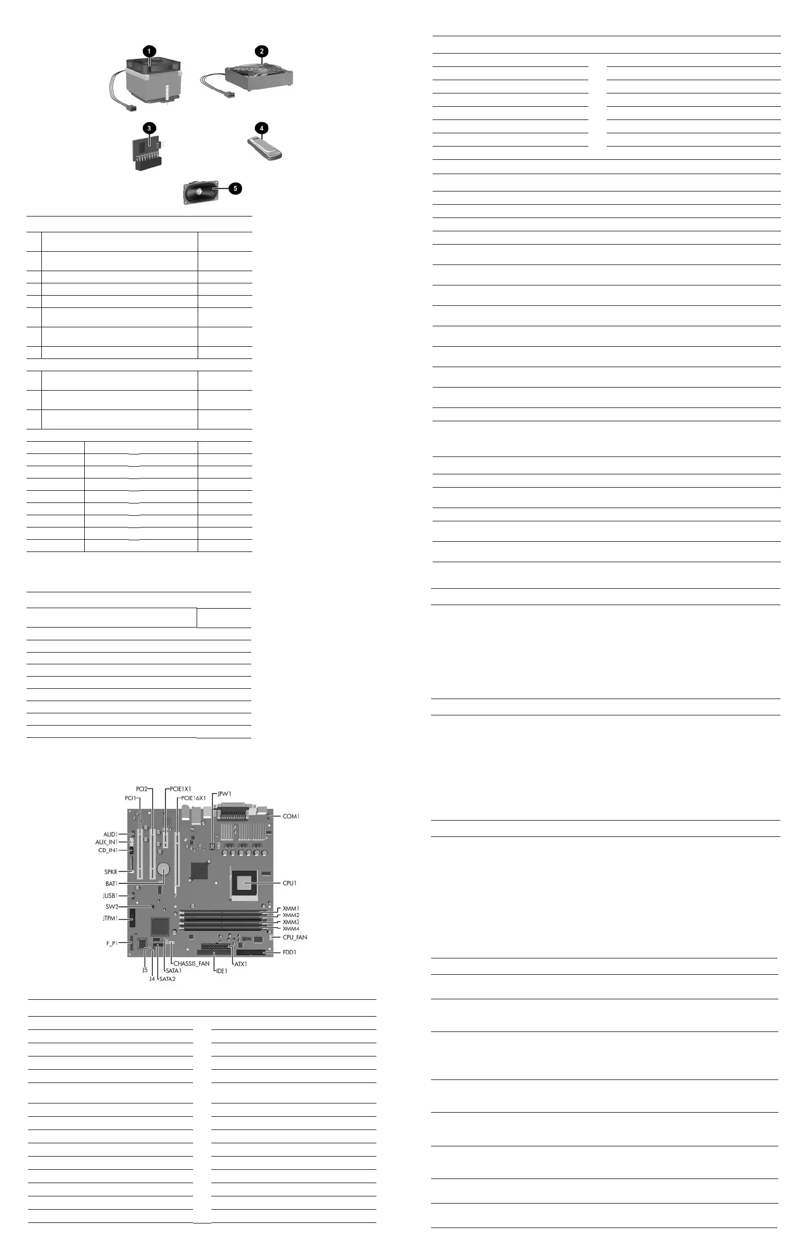
System Board Connectors and Jumpers (position of some untitled components may vary in location)
ATX1 Main power connector (24 pin) JTPM1 TPM security module
AUD1 Front I/O panel audio JUSB1 Front USB connector
AUX_IN1 Aux audio in PCI1 PCI socket 1
BAT1 Battery PCI2 PCI socket 2
CD_IN1 CD audio in PCIE1X1 PCI Express x1 connector
CHASSIS_
FAN
System fan PCIE16X1 PCI Express x16 connector
COM1 Flying serial port SATA1 SATA drive
CPU_FAN Processor fan SATA2 SATA drive
CPU1 Processor socket SPKR Internal audio
F_P1 Hood sensor SW2 CMOS switch
FDD1 Diskette drive XMM1 Memory socket
IDE1 IDE drive connector XMM2 Memory socket
J4 Boot block (default = off) XMM3 Memory socket
J5 Password enable (default = off) XMM4 Memory socket
JPW1 4-pin aux power connector
System Hardware Interrupts
IRQ System Function IRQ System Function
0 Reserved, Timer Interrupt 12 Onboard Mouse Port
1 Reserved, Keyboard Buffer Full Coprocessor 13 Reserved, Numeric Port
4 Serial Port (COM 1) 14 Primary (IDE) Controller
5 PCI System Management 15 Secondary (IDE) Controller
6 Diskette Drive Controller 19 Integrated Graphics (GPU)
8 Real-Time Clock Controller 21 Integrated Audio/USB Host
9 ACPI Compliant System 22 Network Interface Card (NIC)
Computer Diagnostic LEDs (on front of computer)
LED Color LED/Beep Activity State/Message
Power Green On (S0) Computer on
Power Green 1 blink every 2 seconds (S1) Suspend mode
Power Green 1 blink every 2 seconds (S3) Suspend to RAM
Power Red# 2 blinks and beeps 1 second
apart
CPU thermal shutdown
Power Red# 3 blinks and beeps 1 second
apart
CPU not installed
Power Red# 4 blinks and beeps 1 second
apart
Power supply overload
Power Red# 5 blinks and beeps 1 second
apart
Pre-video memory error
Power Red# 6 blinks and beeps 1 second
apart
Pre-video graphics card error
Power Red# 7 blinks 1 and beeps second
apart
System board failure (detected prior to video)
Power Red# 8 blinks and beeps 1 second
apart
Invalid ROM checksum
Power Red# 9 blinks and beeps 1 second
apart
System power on but is unable to boot
Hard Drive Green Blinking Hard drive activity
#Blinking codes are repeated after a two second pause. Beeps stop after fifth iteration, but LEDs continue until problem
is resolved.
Keyboard Diagnostic LEDs, PS/2 Keyboards Only
LED Color LED Activity State/Message
Num Lock Green On ROMPaq diskette or ROMPaq CD not present,
is bad, or drive not ready.
Caps Lock Green On Enter password.
Num, Caps,
Scroll Lock
Green Blink on in sequence, one at a
time—N, C, SL
Keyboard locked in network mode.
Num, Caps,
Scroll Lock
Green On Boot Block ROM Flash successful. Turn power
off, then on to reboot.
# Diagnostic lights do not flash on USB keyboards.
Clearing CMOS Using Computer Setup
The computer's configuration (CMOS) stores password information and information about the computer’s configuration.
To clear and reset the configuration, perform the following procedure:
✎
This is the preferred method for clearing CMOS. However, if you cannot access Computer Setup,
refer to the next section for instructions on using the CMOS switch to clear CMOS.
1. Turn on or restart the computer. If you are in Microsoft Windows, click Start > Shut Down > Restart.
2. As soon as the computer is turned on, press and hold the F10 key until you enter Computer Setup.
✎
If you do not press F10 at the appropriate time, you must restart the computer and press and hold
F10 until you enter Computer Setup.
3. Use the arrow keys to select Load Optimized Defaults, then press Enter.
4. To apply and save changes, press F10, or select Save & Exit Setup and press Enter.
Clearing CMOS Using the CMOS Switch
The computer's configuration (CMOS) may occasionally be corrupted. If it is, it is necessary to clear the CMOS
memory using switch SW2.
To clear and reset the configuration, perform the following procedure:
1. Prepare the computer for disassembly.
Ä
CAUTION: You must disconnect the power cord from the power source before sliding the Clear CMOS
switch (NOTE: All LEDs on the board should be OFF). The CMOS switch will not clear CMOS if the
power cord is connected.
2. Remove the access panel.
3. Slide the CMOS button located on the system board and hold it for 5 seconds.
4. Replace the access panel.
5. Turn the computer on and run F10 Computer Setup (Setup Utility) to reconfigure the system.
Disabling or Clearing the Power-On and Setup Passwords
1. Turn off the computer and any external devices, and disconnect the power cord from the power outlet.
2. With the power cord disconnected, press the power button again to drain any residual power from the computer.
3. Remove the access panel.
4. Locate the header and green jumper labeled J5.
5. Remove the jumper from pins 1 and 2. Place the jumper over either pin 1 or pin 2, but not both, to avoid losing it.
6. Replace the access panel.
7. Plug in the computer and turn on power. Allow the operating system to start, which clears current passwords and
disables the password features.
8. To re-enable the password features, repeat steps 1-3, then replace the jumper on pins 1 and 2.
9. Repeat steps 6-8, then establish new passwords in Computer Setup.
Refer to the Computer Setup (F10 Setup) instructions to establish new passwords.
Computer Setup (F10) Utility Features (not all features may be available)
System
Information
Displays
Standard
CMOS
Features
Date
Time
PATA IDE Channel 0 Master
PATA IDE Channel 1 Master
PATA IDE Channel 2 Master
Drive A
Floppy 3 Mode Support
Halt On
POST Delay
Advanced
BIOS
Features
Removable Device Boot
Priority
Hard Disk Boot Priority
CD-ROM Boot Priority
Network Boot Priority
MBR Security
Quick Power On Self Test
First Boot Device
Second Boot Device
Third Boot Device
Fourth Boot Device
Boot Up NumLock Status
APIC Function
MPS Version Control for OS
HDD S.M.A.R.T. Capability
BIOS Write Protection
Advanced
Chipset
Features
Internal Video Mode
AGP Aperture Size
UMA Frame Buffer Size
Video Display Devices
Auto Detect PCI Clk
Spread Spectrum
Integrated
Peripherals
South OnChip IDE Device
South OnChip PCI Device
Init Display First
Surroundview
OnChip USB Controller
Front Panel USB Port
Onboard FDC Controller
Onboard Serial Port
Onboard Parallel Port
Parallel Port Mode
ECP Mode Use DMA
Power
Management
Setup
ACPI Function
ACPI Suspend Type
After AC Power Loss
PowerOn by PCI Card
AMD Cool’n’Quiet
RTC Alarm Resume
Date (of Month)
Resume Time
PnP/PCI
Configuration
Reset Configuration Data
Resources Controlled By
IRQ Resource
PCI/VGA Palette Snoop
Assign IRQ for VGA
Assign IRQ for USB
PC Health
Status
System Information
Load Optimized Defaults
Set Supervisor Password
Set User Password
Save & Exit Setup
Exit Without Saving
 Loading...