EasyManua.ls Logo

HP FP1707

HP FP1707
77 pages
To Next Page IconTo Next Page
Loading...
17" LCD Color Monitor HP FP1707
1
Service
Service
Service
Horizontal Frequency
24- 83 kHz
TABLE OF CONTENTS
Description Page Description Page
SAFETY NOTICE
ANY PERSON ATTEMPTING TO SERVICE THIS CHASSIS MUST FAMILIARIZE HIMSELF WITH THE CHASSIS
AND BE AWARE OF THE NECESSARY SAFETY PRECAUTIONS TO BE USED WHEN SERVICING ELECTRONIC
EQUIPMENT CONTAINING HIGH VOLTAGES.
CAUTION: USE A SEPARATE ISOLATION TRANSFOMER FOR THIS UNIT WHEN SERVICING
Table Of Contents.......…..............................…........1
Revision List.…..................................……......2
1. Monitor Specification............................………........3
2. LCD Monitor Description……………………….......4
3. Operation Instruction…………..............……...........5
3.1.General Instructions.........................…...........5
3.2. Control Button…………….….........……...............5
3.3 Adjusting the Picture...........................…............6
4. Input/Output Specification......……………............9
4.1. Input Signal Connector............……….................9
4.2. Factory Preset Display Modes......…..................10
4.3. Power Supply Requirements..............................10
5. Panel Specification.....………………..................11
5.1.General Feature…..........................................11
5.2. Optical Characteristics…………………………12
6. Block Diagram……...................………................13
6.1 Software Flow Chart……………………………...13
6.2. Electrical Block Diagram……………..….......15
7. Schematic……………......................................17
7.1 Main Board..……….......................................17
7.2 Power Board.…….……....................................23
7.3 Key Board.……..……....................................25
8.PCB Layout…...…….......................................26
8.1.Main Board………........................................26
8.2.Power Board……….........................................28
8.3.Key Board………............….......................30
9. Maintainability……….......................................31
9.1.Equipments and Tools Requirement..............31
9.2.Trouble Shooting………..............................32
9.2.1 Main Board………………..............................32
9.2.2 Power Board……….……..............................34
9.2.3 Key Board………….……..............................36
10.White-Balance, Luminance adjustment...37
11.Mechanical Instructions………….…...….......39
12.Monitor Exploded View…….…………....….......45
13.BOM List……………….…………………………46
14.Different Parts List….........................................62
Question and Answer IconNeed help?

Do you have a question about the HP FP1707 and is the answer not in the manual?

HP FP1707 Specifications

General IconGeneral
Screen Size17 inches
Resolution1280 x 1024
Aspect Ratio5:4
Brightness250 cd/m²
Response Time8 ms
ConnectivityVGA
Panel TypeTN
Viewing Angle (Horizontal)160 degrees
Viewing Angle (Vertical)160 degrees
InputAnalog
Weight4.2 kg

Summary

Revision List

1. Monitor Specification

2. LCD Monitor Description

Monitor Block Diagram

Visual representation of the monitor's main components and their interaction.

3. Operation Instructions

3.1 General Instructions

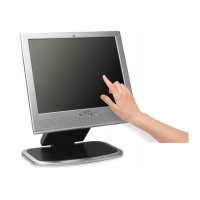
Basic steps for powering on and connecting the monitor to a PC.

3.2 Control Button

Details on the front panel control buttons and their respective functions.

Using the Onscreen Display (OSD)

Guide on navigating and utilizing the monitor's On-Screen Display menu system.

3.3 Adjust the Picture

OSD Menu Selections

Explanation of available OSD menu options and their functions for picture adjustment.

4. InputOutput Specification

4.1 Input Signal Connector

Pin assignments and types for VGA and DVI input connectors.

5. Panel Specification

5.1 General Feature

Key physical and performance specifications of the LCD panel.

Absolute Maximum Ratings

Critical operational limits and electrical characteristics for panel safety.

5.2 Optical Characteristics

Performance metrics related to the display's visual output, like contrast and viewing angle.

6. Block Diagram

6.1 Software Flow Chart

Illustrates the operational logic and decision points within the monitor's software.

6.2 Electrical Block Diagram

High-level overview of the monitor's electrical system architecture.

7. Schematic

7.1 Main Board

Detailed circuit diagram for the monitor's main processing board.

7.2 Power Board

Circuit diagram detailing the power supply and distribution components.

7.3 Key Board

Schematic illustrating the connections and components of the user input key board.

8. PCB Layout

8.1 Main Board

Physical component placement and routing for the main board PCB.

8.2 Power Board

Physical component layout of the power board PCB.

8.3 Key Board

Component layout for the key board PCB, showing switch and LED positions.

9. Maintainability

9.1 Equipments and Tools Requirement

List of necessary tools and equipment for servicing the monitor.

9.2 Trouble Shooting

9.2.1 Main Board

Troubleshooting guide for common issues related to the main board.

9.2.2 Power Board

Diagnostic steps for power-related problems originating from the power board.

9.2.3 Key Board

Troubleshooting procedures for issues with the monitor's button inputs or OSD stability.

10. White- Balance, Luminance Adjustment

11. Mechanical Instructions

12. Monitor Exploded View

13. BOM List

14. Different Parts List

Related product manuals