The fuser power supply has three main components:
● Fuser sleeve. A high-frequency current flows through an induction heating coil in the
fuser sleeve, causing the metal sleeve to heat.
● Thermistors. Two thermistors are in the fuser sleeve: one in the center, and the other at
the end. Each thermistor monitors the temperature in the fuser sleeve.
● Thermoswitch. The thermoswitch is located at the bottom center of the fuser sleeve.
When the fuser is overheating, the switch opens, and power to the induction heating coil
is shut off.
Heater temperature control
The heater temperature control detects the surface temperature of the fuser sleeve and
controls the current flowing to the induction heating coil. The heater temperature control
circuit is shown in
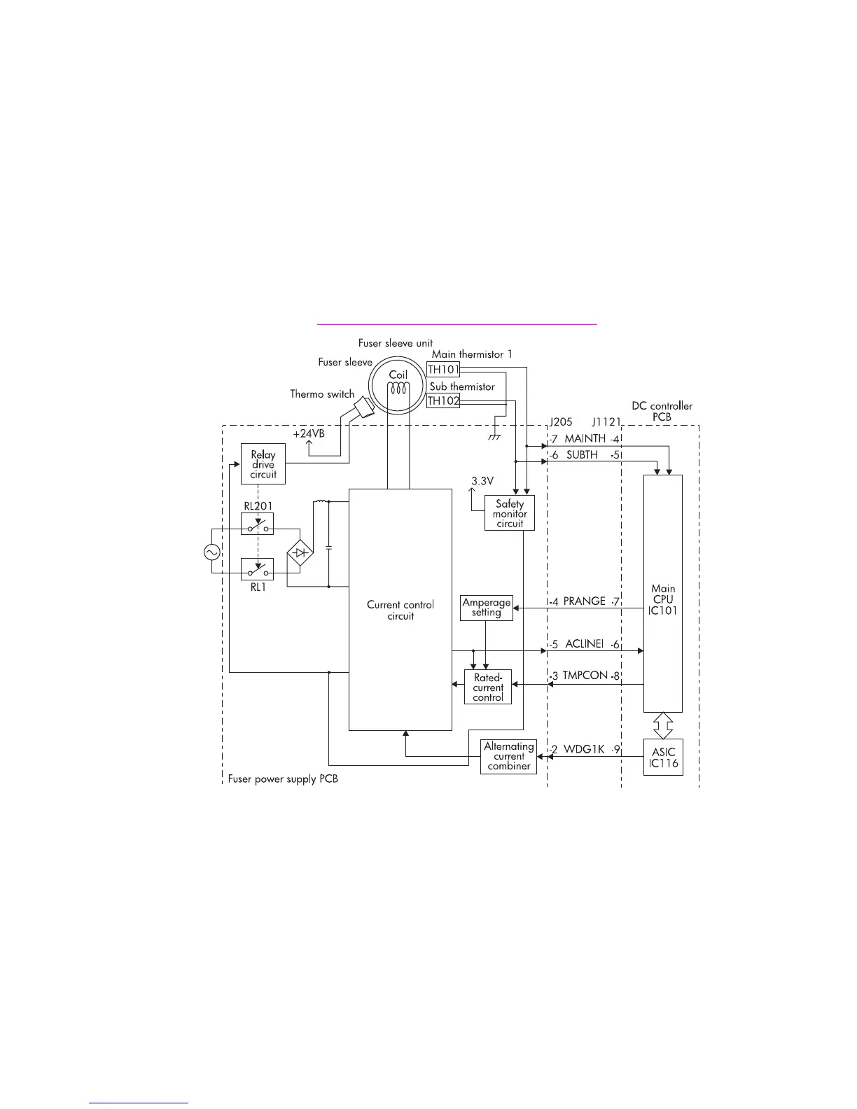
Figure 5-6. Heater temperature control circuit.
Figure 5-6.
Heater temperature control circuit
The two thermistors that are attached to the fuser sleeve (TH101 and TH102) detect the
surface temperature of the fuser sleeve. The main thermistor (TH101) controls the fuser
temperature, and the sub thermistor (TH102) detects overheating at the end of the fuser
sleeve. When the surface temperature of the fuser sleeve increases, resistance of the two
thermistors is reduced, and the voltage of the main thermistor detection signal (MAINTH)
and the sub thermistor detection signal (SUBTH) drops.
The main CPU (IC101) on the DC controller monitors the voltage of the MAINTH and
SUBTH signals. The CPU sends the fuser temperature control signal (TMPCON) according
to the voltage level.
136 Chapter 5 Theory of operation ENWW
 Loading...