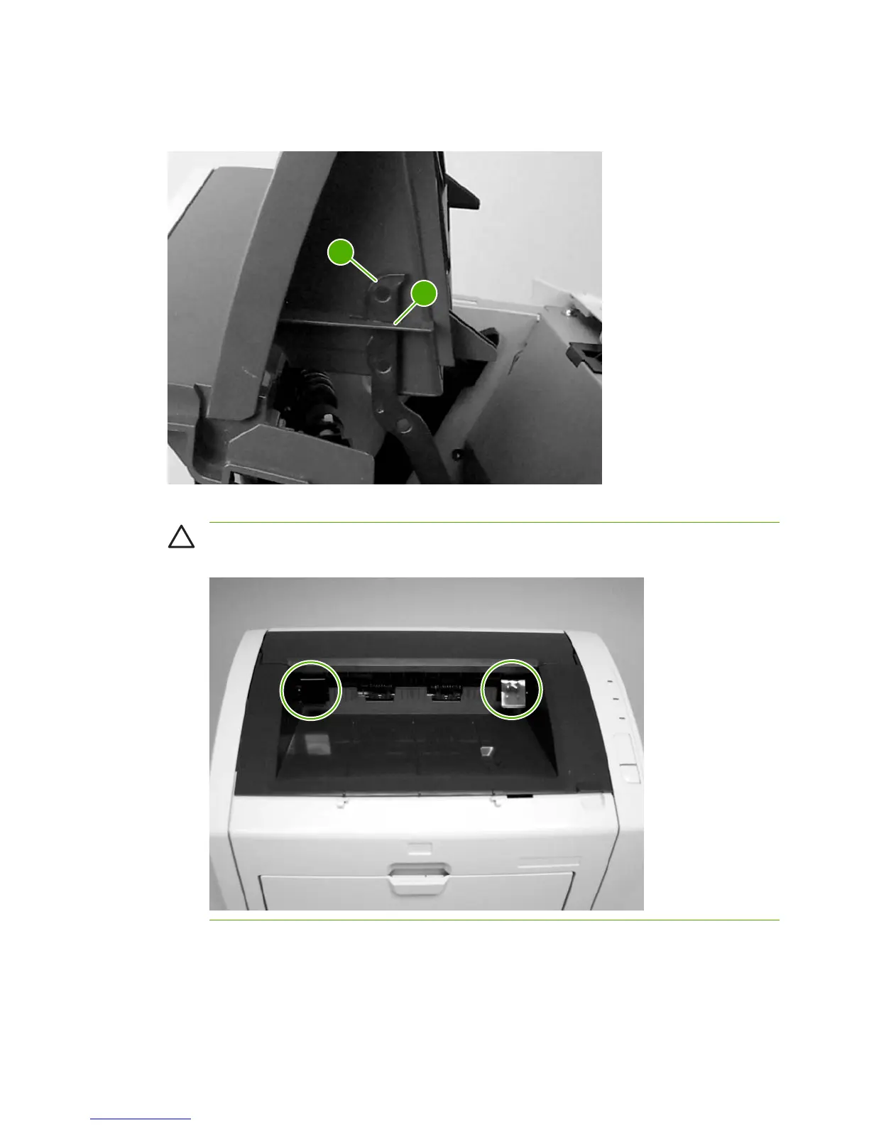
2 Position the top-cover assembly over the pressure-release levers (callout 1), and lower it onto the
chassis. Make sure that the pressure-release levers are inserted through the slots (callout 2) on the
top-cover assembly.
1
2
Figure 5-16 Reinstall the top-cover assembly (2 of 2)
CAUTION Make sure that the two plastic antistatic tabs are correctly positioned. The tabs
must protrude into the output bin area.
74 Chapter 5 Removal and replacement ENWW
 Loading...