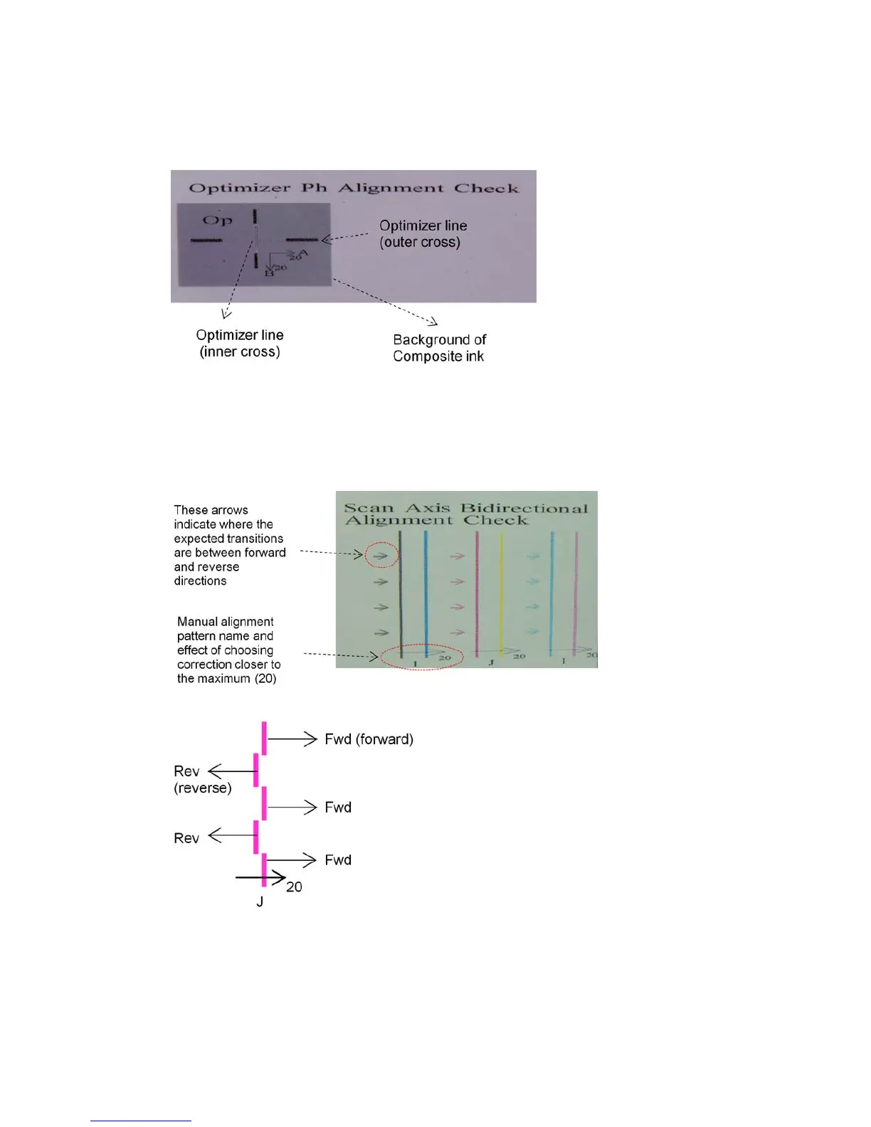
Zone 3: Optimizer printhead alignment check
This area shows the optimizer-to-color printhead alignment. The optimizer is referenced to the black ink. It
works exactly the same as Zone 1. However, there is a background color that highlights the presence of the
optimizer.
Zone 4: Scan-axis bidirectional alignment check
This area shows scan-axis bidirectional alignment between colors. As in the description of the previous areas,
in case of misalignment the bottom arrows indicate the pattern of the manual alignment that will correct the
misalignment (I, J patterns). Also, the ‘20’ label indicates the direction in which the line will be moved if a ‘20’
value is applied.
This pattern is formed by a series of vertical lines, printed unpaired as follows:
The correct bidirectional alignment has been found when the Fwd and Rev lines are perfectly aligned.
The following example shows a misalignment situation with an existing correction J=13, and how to correct
it.
ENWW Possible difficulties with manual alignment 103
 Loading...
