2.
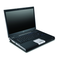
Remove the two Phillips PM2.5×8.0 screws that secure the display assembly to the computer.
3.
Turn the computer display-side up, with the front toward you.
4.
Open the computer to an upright position.
5.
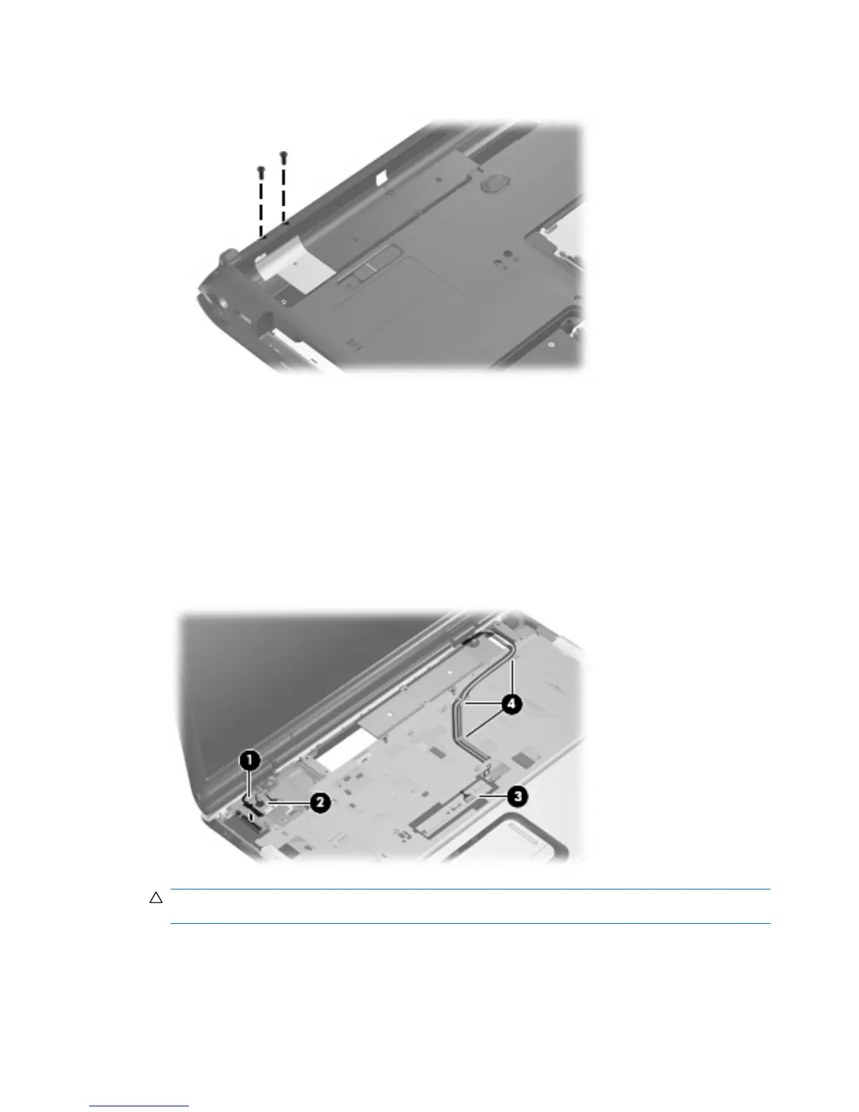
Disconnect the following cables:
(1) Display panel cable
(2) Microphone cable
(3) Camera cable
6. Remove the wireless antenna cables (4) from the routing channels in the top cover.
CAUTION: Support the display assembly when removing the following screws. Failure to support
the display assembly can result in damage to the display assembly and other computer components.
7. Remove the two Phillips PM2.5×8.0 screws (1) and the two silver Phillips PM2.5×5.0 screws (2)
that secure the display assembly to the computer.
70 Chapter 4 Removal and replacement procedures
 Loading...