EL-MF877-00 Page 2
Template Revision B
PSG instructions for this template are available at EL-MF877-01
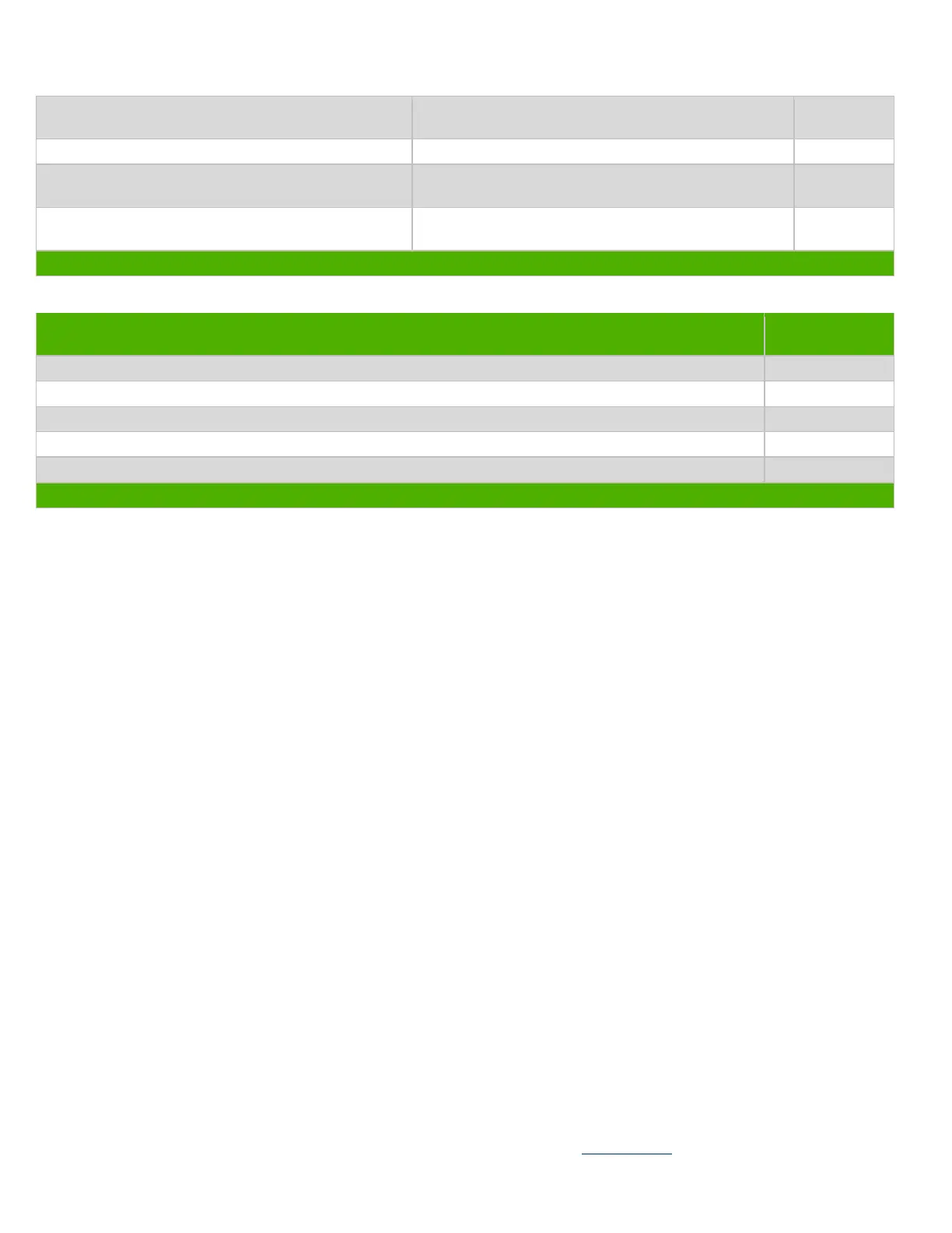
Components and parts containing toner and ink,
including liquids, semi-liquids (gel/paste) and toner
Include the cartridges, print heads, tubes, vent
chambers, and service stations.
Components and waste containing asbestos
Components, parts and materials containing
refractory ceramic fibers
Components, parts and materials containing
radioactive substances
List the type and size of the tools that would typically be used to disassemble the product to a point where components
and materials requiring selective treatment can be removed.
Tool Size (if
applicable)
Description #1 Screwdriver
3.0 Product Disassembly Process
3.1 List the basic steps that should typically be followed to remove components and materials requiring selective treatment:
1. Remove Hinge-door.
2. Release screws for Stand-ASSY, then remove Stand-ASSY
3. Remove HDD-door and Memory-door.
4. Release screw for ODD-module, then use screw driver to push ODD-module out of system.
5. Release screws for Postponement-door, then remove Postponement-door ASSY.
6. Release screw for Rear I/O cover, then remove Rear I/O cover ASSY.
7. Release screws for rear cover, then remove rear cover ASSY.
8. Release screws for converter board, and then remove converter board.(Figure 4)
9. Release screws for Brightness BKT, then remove Brightness ASSY.(Figure 3)
10. Release screws for FAN module, then remove it.
11. Release screws for Thermal module on middle frame and M/B, then remove it.
12. Release screws for M/B shielding, then remove M/B shielding ASSY.(Figure 1)
13. Release standoffs for TV BKT, then remove TV BKT and standoffs.
14. Release screws for M/B, then remove it from middle frame.
15. Release RTC battery from M/B.(Figure 1: highlighted in red zone)
16. To remove ram from M/B.(Figure 2)
17. Release screws for Bluetooth module, Antenna, Camera module and Speaker ASSY, then remove all of them.
18. Release screw for HDD, then remove HDD ASSY.
19. Release screws for Power board, then remove it.(Figure 5)
20. Release screws from Panel-ASSY to Bezel, then remove Panel-ASSY (include middle frame ASSY).
21. Release screws for Panel-ASSY, then remove middle-frame.(Figure 6 )
3.2 Optional Graphic. If the disassembly process is complex, insert a graphic illustration below to identify the items
contained in the product that require selective treatment (with descriptions and arrows identifying locations).
 Loading...