2.
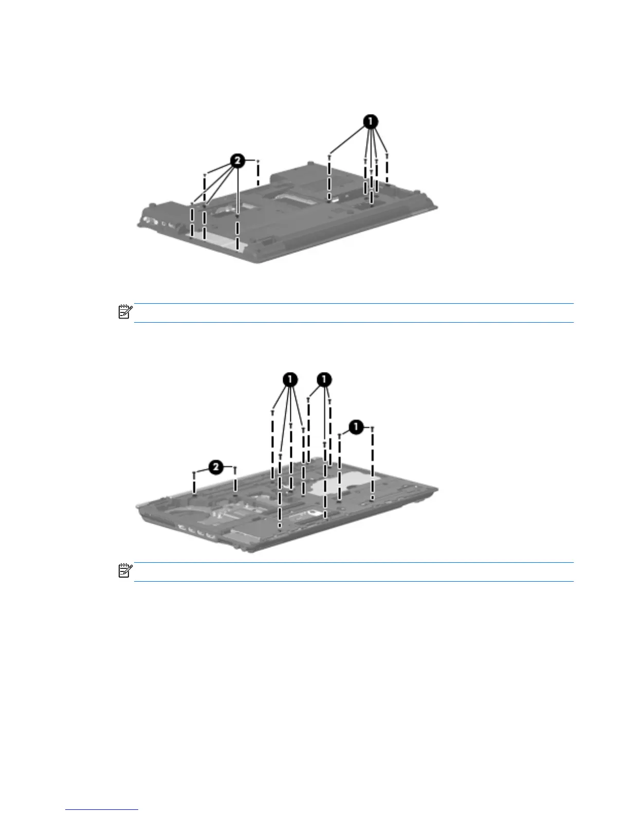
Remove the five slotted Torx T8M2.5×7.0 screws (1) (in the mass storage device bay) and the five
Phillips PM2.0×3.0 screws (2) (in the optical drive and battery bays) that secure the top cover to
the base enclosure.
3. Turn the computer right-side up, with the front toward you.
NOTE: Step 4 applies only to computer models equipped with a 15.6-in display assembly.
4.
Remove the nine slotted Torx T8M2.5×7.0 screws (1) and the two slotted Torx T8M2.5×11.0
screws (2) that secure the top cover to the base enclosure.
NOTE: Step 5 applies only to computer models equipped with a 14.0-in display assembly.
Component replacement procedures
129
 Loading...