1-13
Introducing the Switch
Front of the Switches
LED Mode Select Button and Indicator LEDs
The operation of the Mode LED is controlled by the LED Mode select button,
and the current setting is indicated by the LED Mode indicator LEDs near the
button. Press the button to step from one view mode to the next.
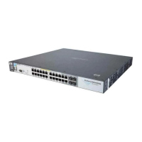
Figure 1-10. Example of Indicator LEDs on an HP ProCurve 24 port Switch
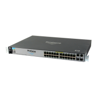
Figure 1-11. Example of Indicator LEDs on an HP ProCurve 48 port Switch
Temp
(green/
Orange)
On Switch temperature is normal.
Blink
orange**
An over temperature condition has been detected.
Auxiliary
(green)
Reserved for future development
* The blinking behavior is an on/off cycle once every 1.6 seconds, approximately.
** The blinking behavior is an on/off cycle once every 0.5 seconds, approximately.
Switch
LEDs
State Meaning
Fault
Power
Locator
LED
Mode
Clear
Reset
PoE-Integrated 10/100/1000Base-T Ports (1
Te st
Tm p
Status
PoE
Fan
Usr
FDx
Spd
PoE
Act
*
12
10864
2
11
97
5
3
1
Link
Mode
Link
Mode
Console
Auxiliary Port
Status of the Back
Mdl
RPSEPS
ProCurve Switch
3500yl-24G
J8692A
Spd mode: off = 10 Mbps
flash = 1
00 Mbps
on = 1000 Mbps
*
PoE
Port LEDs Link
and Mode
Expansion Module LED
LED Mode select button
and indicator LEDs
Fault
Power
Locator
LED
Mode
Clear
Reset
PoE-Integrated 10/100/1000Base-T
Tes t
Tm
p
Status
PoE
Fan
*
Spd mode: off = 10 Mbps, flash = 100 Mbps, on = 1000 Mbps
FDx
Spd
PoE
Act
*
12
10
864
2
119
7
5
3
1
Link
Mode
Link
Mode
Status of the Back
Mdl RP
SEPS
ProCurve Switch
3500yl-48G
J8692A
24
222018
16
14
232119171513
Link Mode
Link
Mode
Usr
PoE
LED Mode select button
and indicator LEDs
Port LEDs Link
and Mode
Expansion Module LEDs
 Loading...