EL-MF877-00 Page 2
Template Revision B
PSG instructions for this template are available at EL-MF877-01
Components, parts and materials containing
refractory ceramic fibers
0
Components, parts and materials containing
radioactive substances
0
2.0 Tools Required
List the type and size of the tools that would typically be used to disassemble the product to a point where components
and materials requiring selective treatment can be removed.
Tool Description Tool Size (if
applicable)
Trox Driver T10/T15
Philips Screw Driver #2
Flat Head Screw Driver Medium
3.0 Product Disassembly Process
3.1 List the basic steps that should typically be followed to remove components and materials requiring selective treatment:
1. System Board Battery - Locate the battery on the system board. Use a medium flat head screwdriver or fingers to
remove the battery and dispose of properly
2. Capacitors=>2.5CM - Remove the power supply from the system using a T-15 driver. With #2 Philips screw driver,
remove the screws securing the top cover, then locate the capacitors and pry from the PCB with a medium flat head
screw driver and dipose of properly
3. BBWC Battery – With a medium flat head screw driver remove the BBWC battery and dispose of properly
4.
5.
6.
7.
8.
3.2 Optional Graphic. If the disassembly process is complex, insert a graphic illustration below to identify the items
contained in the product that require selective treatment (with descriptions and arrows identifying locations).
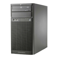
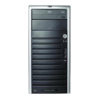
Attachment 1- Expanded view
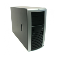
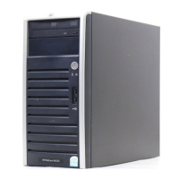
Attachment 2 – System Battery Location
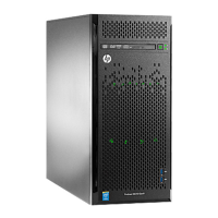
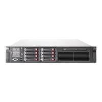
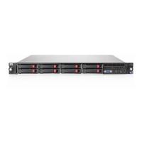
Attachment 3- Location of BBWC Battery
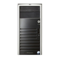
Attachment 4,5,6,7- Capacitor location by model number of supply
 Loading...