Component identification 82
Item Description
27
Processor socket 1 (populated)
System maintenance switch
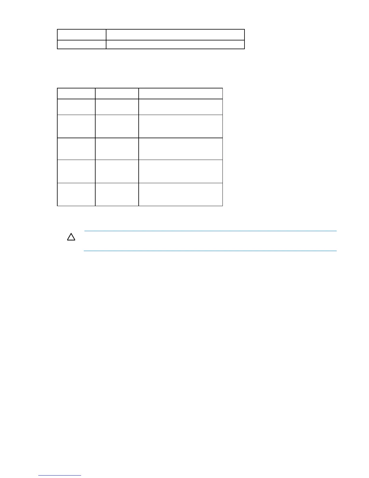
The system maintenance switch (SW2) is a twelve-position switch that is used for system configuration.
Position Description Function
S1
iLO security Off = iLO security enabled.
On = iLO security disabled.
S2
Configuration
lock
Off = Able to change system
configuration.
On = System configuration locked.
S5
Password
protection
override
Off = Password is enabled
On = Password is disabled
S6
Invalidate
configuration
Off = No function
On = ROM treats the system
configuration as invalid.
S3, S4, S7,
S8, S9, S10,
S11, S12
Reserved Reserved
When the system maintenance switch position 6 is set to the On position, the system is prepared to erase all
system configuration settings from both CMOS and NVRAM.
CAUTION: Clearing CMOS and/or NVRAM deletes configuration information. Be sure to
properly configure the server or data loss could occur.
NMI header
The NMI header enables administrators to perform a memory dump before performing a hard reset. Crash
dump analysis is an essential part of eliminating potential reliability issues, such as hangs or crashes in
operating systems, device drivers, and applications. Many crashes can freeze a system, requiring you to
perform a hard reset. Resetting the system erases any information that supports root cause analysis.
Systems running Microsoft® Windows® experience a blue-screen trap when the OS crashes. When this
happens, Microsoft® recommends that system administrators perform an NMI event by temporarily shorting
the NMI header with a jumper. The NMI event enables a hung system to become responsive again.
For additional information, see the HP website
(http://h20000.www2.hp.com/bc/docs/support/SupportManual/c00797875/c00797875.pdf).
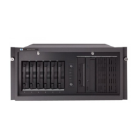
SAS and SATA device numbers
With optional drive cages installed, the server supports up to 24 SFF drives or up to 18 LFF drives. The server
does not support mixing SFF and LFF drives.
HP recommends that you populate drive bays starting with the lowest SAS or SATA device number. Drives
are numbered from left to right in each component box. Component boxes are numbered 1 through 3, from
bottom to top.
 Loading...