List the type and size of the tools that would typically be used to disassemble the product to a point where components
and materials requiring selective treatment can be removed.
Tool Size (if
applicable)
3.0 Product Disassembly Process
3.1 List the basic steps that should typically be followed to remove components and materials requiring selective treatment:
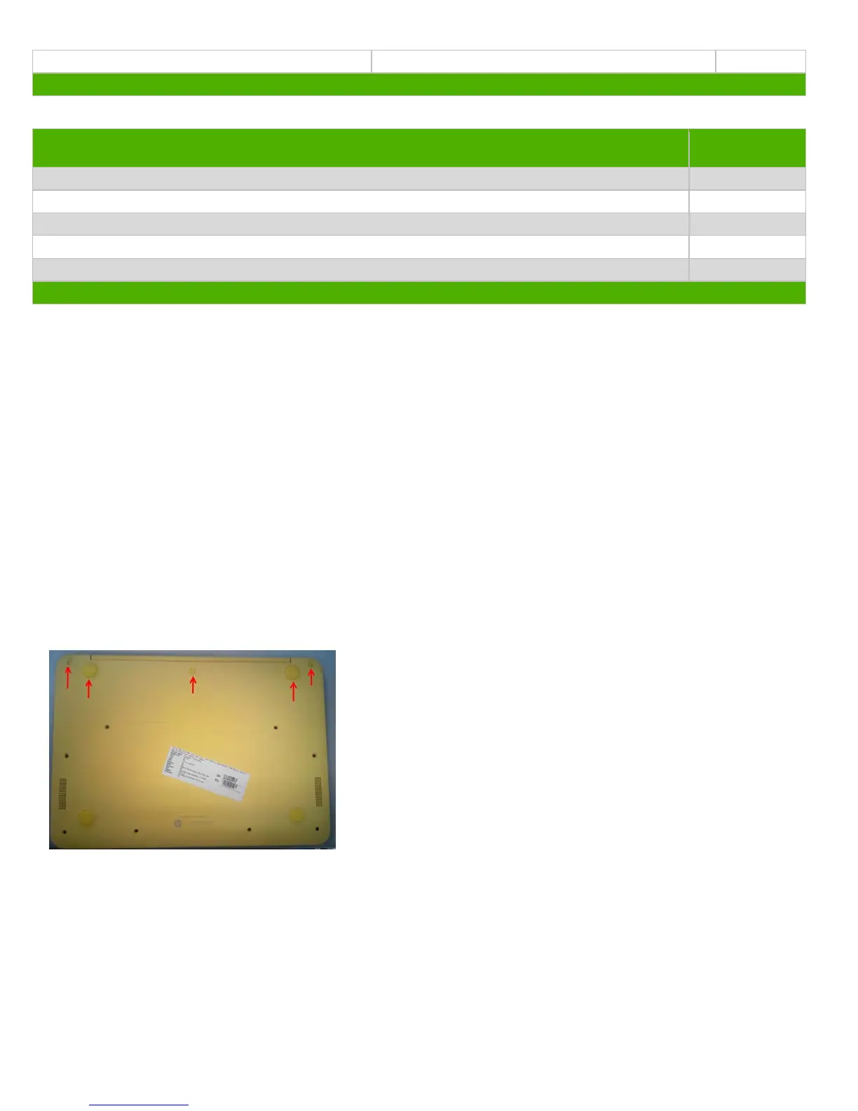
1. Release rear side rubber foot in bottom side of base case (Figure 1)
2. Release screws in bottom side of base case
3. Pull up Top assy (Figure 2)
4. Remove Battery cable/ Power FFC/ TP FFC/ KeyBoard membrane (Figure 3)
5. Release TOP assy (Figure 4)
6. Relase Hinge screws and Remove LVDS cable & antenna cable and LCD ASSY (Figure 5)
7. Release speaker cable and Remove USB FFC (Figure 6)
8. Release screws and remove WWAN/ WLAN card(Figure 7)
9. Release screws and remove Battery(Figure 8)
10. Release screws and Remove Rear/Front Speaker and Release DCin Cable(Figure 9)
11. Release screws and Remove USB Board/ Main Board and DC in cable(Figure 10)
12. Remove CPU EMI bkt (figure 11)
13. Release screw and Remove Power Board & Remove TP FFC and (Figure 12)
14. Release screw and Remove Touch Pad on Top Assy(figure 13)
3.2 Optional Graphic. If the disassembly process is complex, insert a graphic illustration below to identify the items
contained in the product that require selective treatment (with descriptions and arrows identifying locations).
+
1.
2.