EasyManua.ls Logo

HPI Racing Hot Bodies D812 User Manual

HPI Racing Hot Bodies D812
40 pages
To Next Page IconTo Next Page
Page #1 background imageLoading...
Page #1 background image
Vol.1 109891
En Jp
HB D812 KIT
De Fr
Instruction Manual
取扱説明書 
En
Bauanleitung
De
Fr
Manuel de montage
Question and Answer IconNeed help?

Do you have a question about the HPI Racing Hot Bodies D812 and is the answer not in the manual?

HPI Racing Hot Bodies D812 Specifications

General IconGeneral
BrandHPI Racing
ModelHot Bodies D812
CategoryMotorized Toy Car
LanguageEnglish

Summary

Thank You

Safety and Warnings

Highlights critical safety information and warnings throughout the manual.

Caution and Attention Symbols

Explains the purpose of caution and attention symbols used in the manual for safety.

Pre-Operation Safety Checks

Lists precautions and checks to perform before operating the R/C model.

Safe Operation Guidelines

Provides guidelines and warnings for safe operation of the R/C model.

Post-Operation Maintenance

Details necessary routine maintenance and post-operation procedures.

Heat, Fire, and Fuel Safety Precautions

Covers safety precautions related to engine heat, fire hazards, and fuel handling.

Equipment Needed

Radio Components

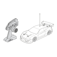
Lists essential radio system components required for the R/C car setup.

Battery Charger Warning

Warns about using incorrect chargers for Ni-MH/LiPo batteries, leading to damage.

Tools and Included Items

Driving Location Warnings

Advises against operating the car in unsafe locations such as water, sand, or public roads.

Step A-01: Shock Assembly (Part 1)

Step A-02: Shock Assembly (Part 2)

Step B-01: Differential Assembly (Front)

Step B-02: Differential Assembly (Rear)

Step C-01: Linkage Assembly (Part 1)

Step C-02: Linkage Assembly (Part 2)

Step D-01: Chassis Assembly

Step E-01: Steering Assembly (Part 1)

Step E-02: Steering Assembly (Part 2)

Step E-03: Suspension Assembly (Part 1)

Step E-04: Suspension Assembly (Part 2)

Step E-05: Suspension Assembly (Part 3)

Step E-06: Drive Shaft Assembly

Step E-07: Drive Shaft Assembly (Part 2)

Step E-08: Chassis Assembly (Part 2)

Step F-01: Steering Linkage Assembly

Step F-02: Suspension Assembly (Part 3)

Step G-01: Drive Shaft Assembly (Part 2)

Step G-02: Chassis Assembly (Part 3)

Step G-03: Suspension Assembly (Part 3)

Step G-04: Chassis Assembly (Part 4)

Step G-05: Chassis Assembly (Part 5)

Step G-06: Drive Shaft Assembly (Part 3)

Step G-07: Drive Shaft Assembly (Part 4)

Step G-08: Chassis Assembly (Part 6)

Step H-01: Chassis Assembly (Part 7)

Step 1-01: Servo Installation (Part 1)

Step 1-02: Servo Installation (Part 2)

Step 1-03: Electronics Installation

Step J-01: Body Mount Assembly

Step K-01: Engine Mount Assembly

Step K-02: Engine Installation

Step K-03: Air Filter Installation

Step K-03: Throttle Linkage Setup

Setting Neutral

Adjusts the throttle linkage for neutral position without brake drag.

Setting Full Throttle

Adjusts the throttle linkage for full throttle, ensuring the carburetor is fully open.

Setting Full Brake

Adjusts the throttle linkage for full brake, ensuring the brake mechanism functions correctly.

Step L-01: Body Mounting

Step M-01: Body Preparation

Step M-02: Body Mounting (Part 2)

Related product manuals