The Techtest Limited 503 Series Emergency Locator Transmitter (ELT) is a battery-powered device designed to provide critical emergency frequency operation at 121.5 MHz, 243.0 MHz, and 406.025 MHz upon activation. It can be configured as a fixed or fixed/portable system, offering versatility for various aircraft installations.
Function Description:
The primary function of the 503 Series ELT is to transmit distress signals on three distinct frequencies, aiding in the location and rescue of aircraft and personnel in emergency situations. The 121.5 MHz and 243.0 MHz frequencies are used for homing by search and rescue teams, while the 406.025 MHz frequency transmits coded digital messages to the COSPAS-SARSAT satellite system, providing more precise location data.
The system incorporates several key components to ensure reliable operation:
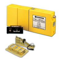
- ELT 503-1: This is the core transmitting unit, housed in a high-visibility yellow thermoplastic casing. It is self-contained with its own long-life battery, control switch, and antenna port. In portable mode, it can operate as a standalone unit with an attached antenna.
- G-Switch (503-7 Series, 503-19 Series, 503-35 Series & 503-36 Series): An essential part of the fixed ELT system, the G-Switch automatically triggers the ELT into transmission when the 'G' force exceeds a preset limit in two or three bidirectional axes, depending on the model. This ensures activation even if the aircrew cannot manually activate the beacon. It is permanently connected to the ELT via a 9-pin connector.
- Remote Controller (503-4, 503-17, 503-20, 503-52 & 503-53): This small switch unit allows aircrew to test, reset, or manually activate the ELT from their positions. It features an indicator lamp and an internal sounder to provide audible and visual system status. The 503-52 model is designed for vertical mounting.
- AF/AP ELT Cockpit Control Panel (503-51): Similar to the remote controller, this panel offers additional features such as a fault indicator and an inhibit switch, providing more comprehensive control and status monitoring.
- Mounting Rack (A0637 Series): These racks are designed to secure the G-Switch and ELT to the airframe in an optimal attitude to withstand high 'G' forces during an emergency. Fixed mounting trays (A0637-1, A0637-3, A0637-5) are secured by Dzus fasteners or screws. Fixed/portable trays (A0637, A0637-6, A0637-8) allow the ELT to be easily withdrawn for portable use, with a stowed portable antenna provided.
- Interface Unit (503-15 Series): This unit is designed to pass GPS data to the ELT, enabling the 406.025 MHz transmission to include precise positional data for satellite relay. It can be JAA (ED62) or FAA (RTC/DO-204) compatible, with the interface type determined by a link in the connector.
- Water Activated Switch (503-23-1): This component provides automatic ELT activation upon immersion in salt or fresh water, enhancing safety in marine environments.
- Antenna: External to the aircraft, a three-frequency antenna transmits the signal. Various antenna types (Figures 12-18) are available for fixed installations, while a portable antenna (Figure 19) is stowed on the mounting tray for use with the ELT in portable mode.
Important Technical Specifications:
- Frequencies: 121.5 MHz, 243.0 MHz, and 406.025 MHz.
- 406.025 MHz Output Power: 5 watts (minimum 24 hours use).
- 121.5 MHz & 243.0 MHz Output Power: 0.1 watts (minimum 48 hours use).
- ELT Battery Life (A0673-1): 5 years installed unused life.
- G-Switch Battery Life: 2.5 years (storage life of 5 years).
- COSPAS-SARSAT Message Protocols: Supports USER-LOCATION (4 minutes resolution), NATIONAL-LOCATION (4 seconds resolution), and STANDARD-LOCATION (4 seconds resolution). STANDARD-LOCATION or NATIONAL-LOCATION protocols are recommended for systems with GPS.
- G-Switch Power Supply: Requires a 28V power supply for system diagnosis.
Usage Features:
- Modular Design: The 503 ELT system is modular, allowing for various configurations to suit specific aircraft requirements.
- Automatic Activation: G-Switch for impact activation and Water Activated Switch for water immersion activation.
- Manual Activation: Remote controllers and cockpit control panels allow aircrew to manually activate the ELT.
- Test Functionality: Built-in test (BIT) system allows for self-testing from the ELT, remote controller, or G-Switch.
- Inhibit Facility: Certain G-Switch variants (e.g., 503-7-3INH, 503-19-2A, 503-35A) include an inhibit facility, allowing a separate switch to disable G-Switch and remote controller activation. The ARM/OFF/ON switch on the G-Switch provides an override, activating the ELT immediately without BIT or GPS encoding.
- GPS Integration: Interface units enable the ELT to transmit the latest onboard positional data via the 406.025 MHz signal.
- Portable Mode: The ELT 503-1 can be easily detached from its fixed mounting rack and used as a portable unit with a dedicated portable antenna.
Maintenance Features:
- Sealed for Life Construction: The ELT beacon is designed for minimal maintenance, with servicing primarily limited to physical inspection and battery replacement.
- Physical Inspection Periodicity:
- Antenna: Daily
- Control Unit: Monthly
- Emergency Locator Beacon: Every 3 months
- Battery Replacement:
- ELT Battery: Every 5 years, or sooner if used for purposes other than Built-in Test.
- G-Switch Battery: Every 2.5 years.
- Troubleshooting (Diagnose Mode): The system's self-test function helps identify faults. If a self-test fails, a "diagnose mode" can be used to pinpoint the failed component (G-Switch or ELT) by interpreting a sequence of bleeps from the G-Switch.
- 2 Bleeps: Communications failure between G-Switch and ELT.
- 3 Bleeps: G Force sensor 0 failure.
- 4 Bleeps: G Force sensor 1 failure.
- 5 Bleeps: G Force sensor 3 failure.
- 7 Bleeps: ELT battery failure.
- 8 Bleeps: ELT RF failure.
- 9 Bleeps: ELT test failure.
- 10 Bleeps: Sounder failure.
- Antenna Maintenance: The antenna and RF feeder should undergo a VSWR test annually using a Techtest Test Set 12-602-8.
- G-Switch Battery Pack Recharging & Conditioning: The G-Switch uses a removable, rechargeable Nickel Metal Hydride battery pack. The charging circuit includes a trickle charge, fast charge, and then returns to trickle charge once fully charged.
- Battery Pack Testing: The battery pack can be tested under load to gauge its condition. Measurements of terminal status (open circuit, with 100 Ohm resistor) and potential (voltage) at different stages (just completed charging cycle, 15 minutes after test on load) provide indicators of battery health. After testing, the battery should be returned to trickle charge.
- Repair: Maintenance beyond physical inspection and battery replacement is generally performed only by the manufacturer.