- -
5
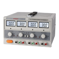
(15) Positive output terminal of master output.
(16) Ground connection terminal of case.
(17) Negative output terminal of master output.
(18) Positive output terminal of slave output.
(19) Ground connection terminal of case.
(20) Negative output terminal of slave output.
(21) Mains power on/off switch.
(22) Fixed 5V positive output terminal.
(23) Fixed 5V negative output terminal.
2.2 USING METHOD
2.2.1 DUAL POWER SUPPLY USED IN INDEPENDENT MODE
2.2.1.1 Move switches 13 & 14 to the up position
2.2.1.2 For constant voltage mode, adjust controls 6&8 clockwise to the maximum position. Move
switches 2&3 to the voltage display position. Switch on the power ON/OFF switch and adjust
controls 5 & 7 to the desired voltage for the master and slave outputs.
2.2.1.3 For constant current mode, switch on the power ON/OFF switch and adjust controls 5&7
clockwise to the maximum position. Adjust controls 6&8 anti-clockwise to the minimum position.
After connecting the load, move switches 2&3 to the current display position. Adjust controls 6&8 to
give the desired current at the master or slave outputs.
2.2.1.4 For current limit protection mode (DC power supply: Output voltage less than 50V, or

 Loading...