Principles and Application Scenarios
Product Overview
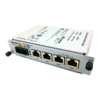
The RTN PI-DC A11 receives one channel of DC power signals and one channel of GE service signals.
The signal coupling module couples DC power signals and GE service signals into P&E signals and outputs the P&E signals
to the P&E port.
The frequencies of DC power signals and GE service signals do not interfere with each other. Therefore, the two types of
signals can be transmitted over the same twisted pair.
DC-DC
processing
mode
DC IN
Signal
coupling
module
GE
P&E
DC-PI working principles
DC-PI
powered
device
UNI-side
device
≤ 100 m
•The PI only couples GE signals and power signals, but does not regenerate or strengthen GE signals. Therefore, the
network cable between the UNI-side device and the powered device must not be longer than 100 m.
•The maximum distance between the PI and the powered device varies depending on the power of the powered device.
For details, see technical specifications.
Maximum
distance between
the PI and
powered device
CAUTION
B
Application Scenarios
A
Principles
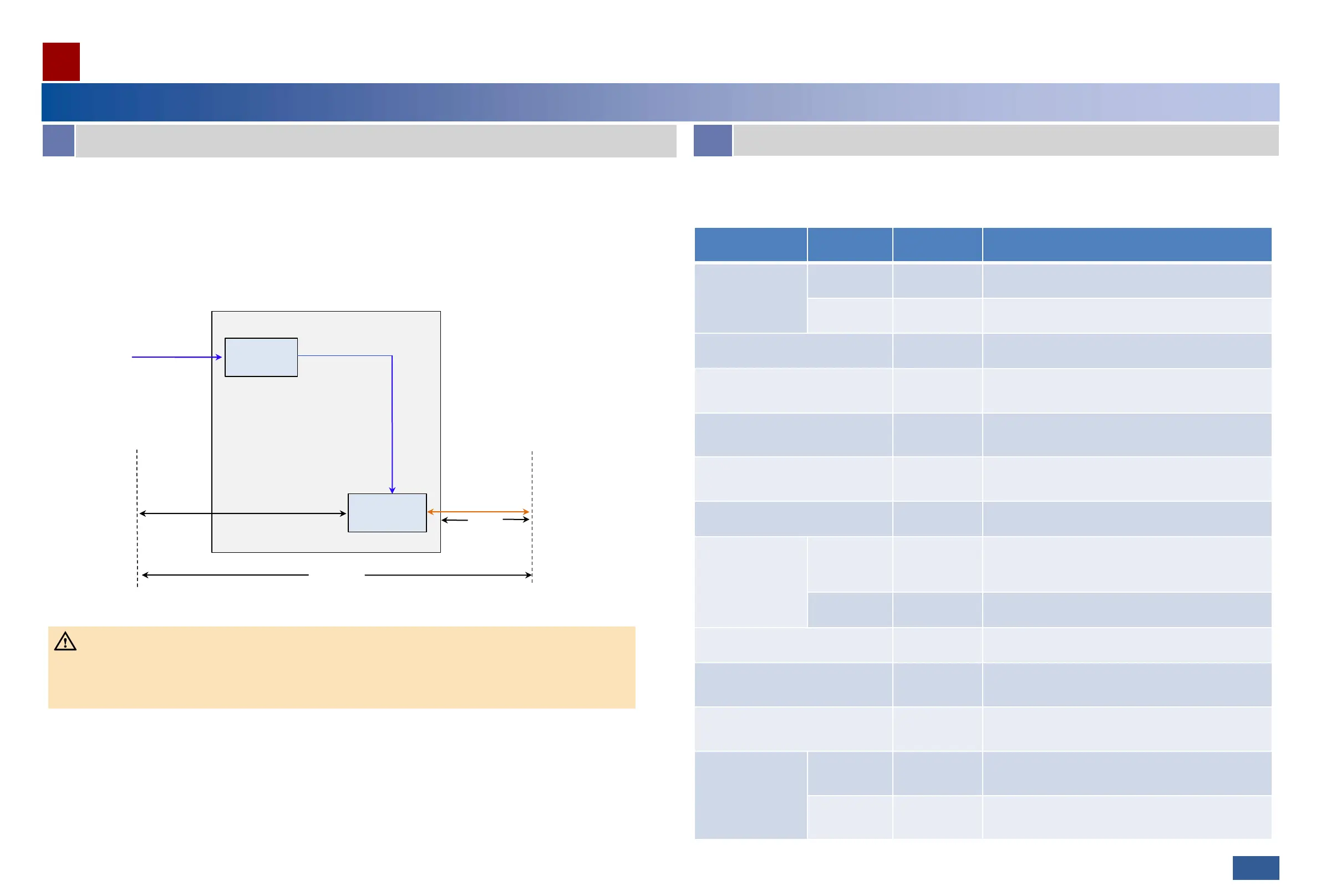
Mapping between powered device types and power supply modes
03
The RTN PI-DC A11 can supply power to OptiX RTN 300 full-outdoor microwave equipment series. The power supply
mode of the PI varies according to powered device type.
Device Type Version
PI Support
(Yes/No)
Power Supply Mode
 Loading...