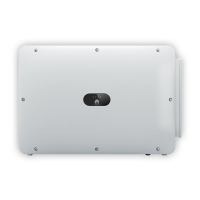
(3) DC input terminals (controlled by
DC SWITCH 2)
(4) DC switch 2 (DC SWITCH 2)
(5) DC input terminals (controlled by
DC SWITCH 3)
(6) DC switch 3 (DC SWITCH 3)
(7) Ventilation valve (8) USB port (USB)
(9) Communications port (COM) (10) Hole for the AC output power
cable
(11) Hole for the tracking system
power cable
Figure 2-6 Port Illustration (Automatic DC Switch)
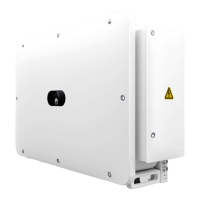
(1) DC input terminals (controlled by
DC SWITCH 1)
(2) DC switch 1
[1]
(DC SWITCH 1)
(3) Reset button 1 (RESET 1) (4) DC input terminals (controlled by
DC SWITCH 2)
(5) DC switch 2
[1]
(DC SWITCH 2)
(6) Reset button 2 (RESET 2)
(7) DC input terminals (controlled by
DC SWITCH 3)
(8) DC switch 3a
[1]
(DC SWITCH 3)
(9) Reset button 3 (RESET 3) (10) Ventilation valve
(11) USB port (USB) (12) Communications port (COM)
(13) Hole for the AC output power
cable
(14) Hole for the tracking system
power cable
Note [1]: If the DC switch rotating handle is at the position , the DC switch
is not completely closed and may not be automatically switched o.
2.3 Label Description
SUN2000-(196KTL-H0, 200KTL-H2, 215KTL-H0)
Series
User Manual 2 Overview
Issue 08 (2021-09-30) Copyright © Huawei Technologies Co., Ltd. 12
 Loading...