Do you have a question about the Huba Control 699 and is the answer not in the manual?
Ensures safe operation according to manual specifications and legal regulations.
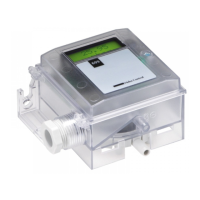
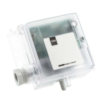
Devices are for process variable indication; operation requires qualified staff and intended use only.
Identifies potential risks from unqualified staff and marks significant hazards with a symbol.
Proper installation and cabling are crucial for interference immunity, using shielded cables.
Verify system depressurization before mounting; avoid high pressure pulses and thermal changes.
Covers voltage versions, cable length considerations for voltage drop, and display lighting behavior.
Vertical mounting with downward pressure connections to drain condensate; maintain distance from magnetic material.
The zero point reset button allows variable installation position and resettable pressure variations.
Diagrams showing connections for 2-wire, 3-wire, and universal configurations.
Identifies DIP-Switch, Zero point reset, terminals, and pressure connectors (P1, P2).
Table shows DIP-Switch settings for different pressure ranges (Range00, Range01, Range10, customer adjustment).
Identifies DIP-Switch, reset, terminals, connectors, potentiometer, and LCD components.
Details components for adjustability 3, including LCD and its receptacle.
Table shows factory settings for pressure ranges via DIP-switch positions.
Illustrates DIP-Switch settings for switchable pressure ranges and signal linearity.
Explains using the turbo potentiometer for continuous adjustment within pressure ranges.
Graphical representation of output signal linearity across pressure ranges for different configurations.
Table detailing factory settings for output signals (Voltage, mA) based on DIP-Switch.
Shows DIP-Switch settings for various output signals and corresponding connection diagrams.
Table indicates factory settings for filter (off/on) and signal response (linear/root extracted).
Illustrates DIP-Switch positions for Filter 'off' and 'on' (1 sec.) with response time explanation.
Table shows factory settings for signal response (linear/root extracted) by DIP-Switch.
Depicts DIP-Switch positions for linear and root extracted response curves with signal/pressure graphs.
Explains normal display and offset adjustment via short/long keypresses.
Diagram illustrating menu navigation for Offset, Display, Unit, and Output settings.
Covers output attitude adjustment, filter settings (0.2s to 20s), and display light control.
Details serial number, uptime, trace, and factory reset options.
Explains normal display, pressure unit selection, and turbopotentiometer adjustment.
Describes selection of output signal type and adjustment of pressure range attitude.
Explains filter response time adjustments and display light on/off settings.
Provides product information (serial number) and factory setting reset procedures.
States CE conformity according to EN 61326-2-3 for electromagnetic compatibility.
| Output signal | 4...20 mA |
|---|---|
| Accuracy | typ. ±0.5 % FS |
| Media temperature | -40...+125°C |
| Electrical connection | M12x1 connector |
| Process connection | G1/4" / G1/2" / 1/4" NPT / 1/2" NPT |
| Protection class | IP67 |