12
FUEL———CARBURETION
CARTER MODEL WCFB-2593-S FOUR-BAR-
REL CARBURETOR
The Carter Model WCFB carburetor is basically two (2)
dual carburetors contained in one assembly. The section
containing the metering rods, accelerating pump and
choke is termed the primary side of the carburetor, the
other section, the secondary side. It has five (5) conven-
tional circuits. They are:
2—Float Circuits
1—Low Speed Circuit
2—High Speed Circuits
1—Pump Circuit
1—Climatic ® Control (Choke) Circuit
FLOAT CIRCUITS
The purpose of the float circuits is to maintain an adequate
supply of fuel at the proper level in the bowls for use by
the low speed, high speed, pump and choke circuits. Pri-
mary and secondary bowls are separated by a partition.
The fuel line connection is on the primary side. Fuel is
supplied to the primary and secondary intake needles and
seats through a passage in the bowl cover. There are two
fine mesh strainer screens in the bowl cover. They are
located at the fuel inlet and at the secondary intake needle
seat.
The bowls are vented to the inside of the air horn by
vertical vent tubes and to atmosphere by drilled passages
in the air horn. Bowl vents are calibrated to provide proper
air pressure above the fuel at all times. The bowl cover
gasket seals the fuel bowl, idle and vacuum passages. To
assure a positive seal, always Use a new bowl cover gasket
when reassembling. An air leak at this point can result in
a performance or economy complaint.
A connecting passage along the outside of the body
effects a balance of the fuel levels and air pressures be-
tween the two bowls.
FIGURE 1—Float Circuit
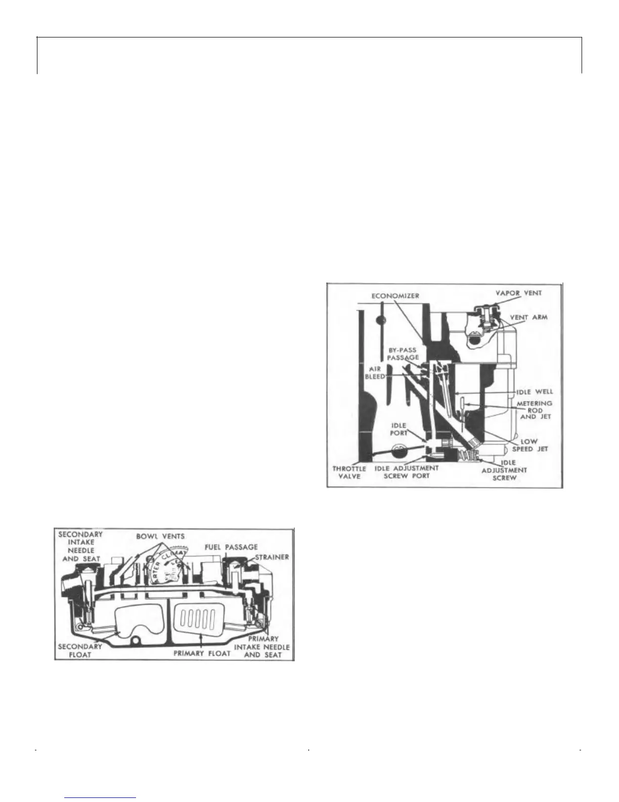
LOW SPEED CIRCUITS
Fuel for idle and early part throttle operation is metered
through the low speed circuit.
Fuel enters the idle wells through the metering rod jets
on the primary side of the carburetor. No idle system is
used in the secondary side of the carburetor.
The low speed jets measure the amount of fuel for idle
and early part throttle operation. The air by-pass, econo-
mizers, and idle air bleeds are carefully calibrated and
serve to break up the liquid fuel and mix it with air as it
moves through the passages to the idle ports and idle
adjustment screw ports. Turning the idle adjustment
screws toward their seats reduces the quantity of fuel
mixture supplied by the idle circuit.
The idle ports are slot shaped. As the throttle valves are
opened more of the idle ports are uncovered allowing a
greater quantity of the fuel and air mixture to enter the
carburetor bores. The secondary throttle valves remain
seated at idle.
FIGURE 2—Low Speed Circuit
Throttle Bore Vapor Vent Passages
Under certain conditions of high, under-hood temperature,
fuel vapor forms in the throttle bores when the engine is
not operating. This vapor accumulation may retard hot
engine starting until sufficient air is drawn into the carbu-
retor to mix with the vapor to form a combustile mixture.
The throttle bore vapor vent passages vent the bores
above the throttle valves to cavities in the underside of the
carburetor flange. Air is admitted to these cavities through
openings in the flange gasket. The air supplied by these
vent passages, when mixed with the accumulated vapor,
forms a more combustible mixture. This improves hot
engine starting.
HIGH SPEED CIRCUITS
Fuel for part throttle and full throttle operation is

 Loading...