FUEL—CARBURETION
13
supplied through the high speed circuits. Main discharge
nozzles are permanently installed and must not be re-
moved in service.
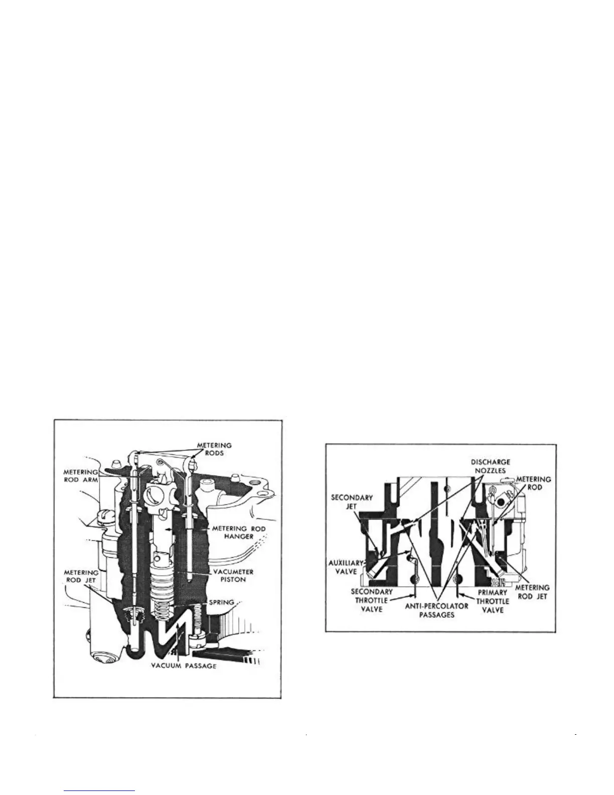
Primary Side
The position of the metering rods in the metering rod jets
control the amount of fuel flowing in the high speed circuit
of the primary side of the carburetor. The position of the
metering rods is dual controlled; mechanically by move-
ment of the throttle, and by manifold vacuum applied to
the vacuum piston on the vacumeter link.
Mechanical Metering Rod Action
During part throttle operation, manifold vacuum pulls the
vacumeter piston, link and metering rod assembly down,
holding the vacumeter link against the metering rod coun-
tershaft arm. Movement of the metering rods will then be
controlled by the metering rod countershaft arm which is
connected to the throttle shaft. This is true at all times that
the vacuum under the piston is strong enough to overcome
the tension of the vacumeter spring.
Vacuum Metering Rod Action
Under any operating conditions (acceleration, hill climb-
ing, etc.), when the tension of the vacumeter spring over-
comes the pull of vacuum under the piston, the metering
rods will move toward their wide-open throttle or power
position.
FIGURE 3—High Speed Circuit Metering Rods
Secondary Side
Fuel for the high speed circuit of the secondary side is
metered at the main metering jets (no metering rods used).
Throttle valves in the secondary side of the carburetor
remain closed until the primary throttle valves have been
opened a predetermined amount. They arrive at wide open
throttle position at the same time as the primary throttle.
This is accomplished by linkage between the throttle levers.
The second set of counterweighted off-set throttle
valves mounted above the secondary throttle valves are
called "auxiliary throttle valves." Air velocity through the
carburetor controls the position of the auxiliary throttle
valves. When the accelerator is fully depressed, only the
primary high-speed circuit will function until there is
sufficient air velocity to overcome the weight of the coun-
terweight on the auxiliary throttle lever and open the
auxiliary throttle valves. When this occurs, fuel will also
be supplied through the secondary highspeed circuit.
The secondary throttle valves are locked closed during
choke operation, to insure faster cold engine starting and
good "warm-up" performance.
Anti-Percolator
To prevent vapor bubbles in the nozzle passages and low
speed wells from forcing fuel out of the nozzles, anti-
percolator passages and calibrated plugs and bushings are
used. Their purpose is to vent the vapors and relieve the
pressure before it is sufficient to push the fuel out of the
nozzles and into the intake manifold. Anti-percolator
plugs and bushings are permanently installed and must not
be removed in service.
FIGURE 4—High Speed and Anti-Percolator
Circuits
PUMP CIRCUIT
The pump circuit is located only in the primary side of the
carburetor.
 Loading...