________________________________________
Axles, Suspension, and Frame 9-59
®
05745159
REAR-FRONT TIEDOWN BRACKET
REPLACEMENT
Removal
1. Remove wheel (Section 6).
2. Remove four locknuts, washers, bolts, washers, and
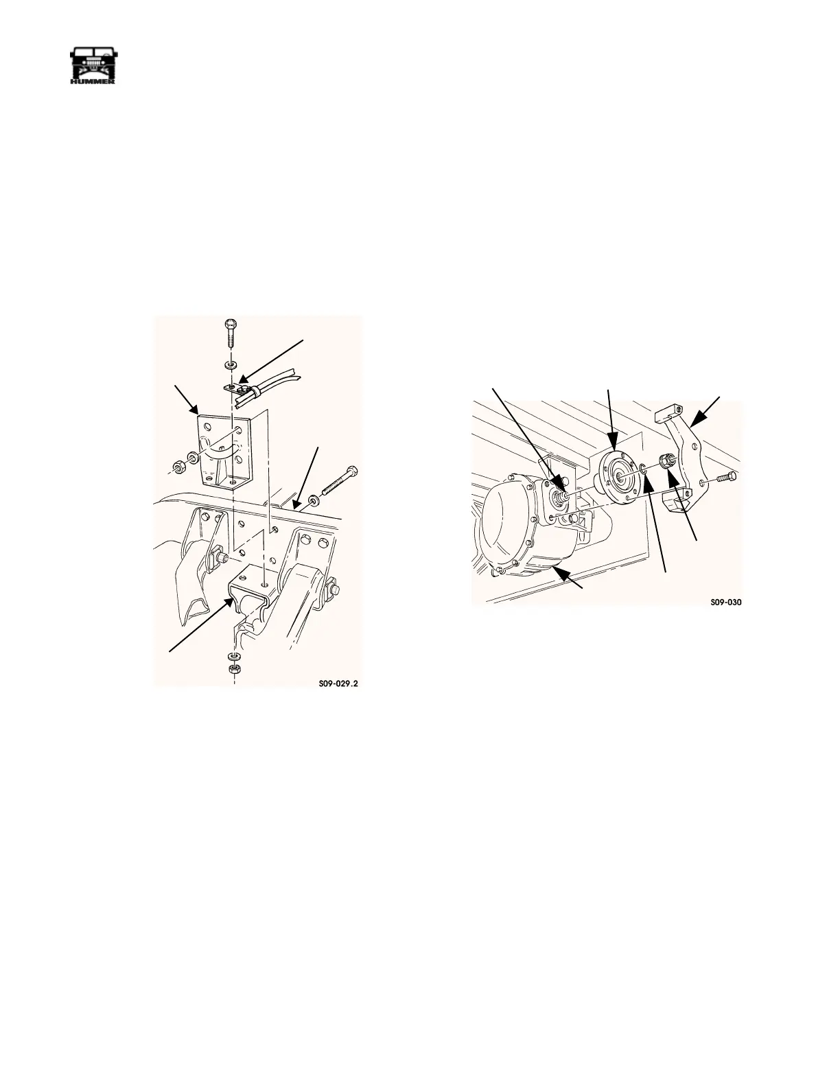
tiedown bracket from frame rail (Figure 9-140).
3. Remove two locknuts, washers, bolts, washers, vent tube/
speed sensor lead mounting bracket, and tiedown bracket
from rear suspension front crossmember mounting
bracket.
Figure 9-140: Rear-Front Tiedown Bracket
Replacement
Installation
1. Install tiedown bracket and vent tube mounting bracket on
rear suspension front crossmember mounting bracket with
two washers, bolts, washers, and locknuts. Tighten lock-
nuts to 90 lb-ft (122 N•m) (Figure 9-140).
2. Install tiedown bracket on frame rail with four washers,
bolts, washers, and locknuts. Tighten locknuts to 261 lb-ft
(354 N•m).
3. Install wheel.
AXLE SUPPORT BRACKET AND SIDE
MOUNTING BRACKET REPLACEMENT
Removal
1. Remove brake caliper and rotor.
2. Remove locknut, seal washer, and output flange from
output shaft. Discard seal washer (Figure 9-141).
3. Remove two bolts and brake adapter from axle.
4. Remove two bolts and washers securing side mounting
bracket to axle (Figure 9-142).
5. Remove two locknuts, washers, bolts, washers, support
bracket, and side mounting bracket from crossmember.
6. Remove two locknuts, washers, bolts, washers, and side
mounting bracket from support bracket (Figure 9-143).
Figure 9-141: Brake Adapter and Output Flange
Replacement
Installation
1. Install side mounting bracket on support bracket with two
washers, bolts, washers, and locknuts (Figure 9-143).
2. Install support bracket and side mounting bracket on
crossmember with two washers, bolts, washers, and
locknuts (Figure 9-142). Do not tighten bolts.
3. Apply thread-locking compound to tapped holes of axle
and install two washers, bolts, and side mounting bracket
on axle. Tighten side mounting bracket bolts to 110-139
lb-ft (149-189 N•m) and support bracket bolts to 90 lb-ft
(122 N•m).
4. Apply thread-locking compound to tapped holes of axle
and install brake adapter on axle with two bolts. Tighten
bolts to 110-139 lb-ft (149-189 N•m) (Figure 9-141).
5. Install output flange on output shaft with seal washer and
locknut. Tighten locknut to 170 lb-ft (231 N•m).
6. Install brake caliper and rotor.
TIEDOWN BRACKET
FRAME RAIL
CROSSMEMBER
MOUNTING
BRACKET
VENT TUBE
SPEED SENSOR LEAD
BRACKET
OUTPUT SHAFT
OUTPUT FLANGE
BRAKE ADAPTER
SEAL WASHER
AXLE
LOCKNUT