EasyManua.ls Logo

Humminbird MHX XNT User Manual

Humminbird MHX XNT
8 pages
To Next Page IconTo Next Page
Page #1 background imageLoading...
Page #1 background image
High Speed Impact-Release Transom Mount Transducer
1
531565-4_C
Installation Overview
B
efore you start the installation, we encourage you to read these instructions carefully in order to get the full
benefit from your Humminbird® accessory.
NOTE: Your transducer may not look exactly like the transducer shown in the illustrations, but it will mount
in exactly the same way.
Supplies: In addition to the hardware supplied with your transducer, you will need a powered hand drill and various
drill bits, various hand tools, including a ruler or straightedge, a level, a 12" plumb line (weighted string or monofilament
line), a marker or pencil, safety glasses and dust mask, marine-grade silicone sealant, and dielectric grease (optional).
You may also need extension cables and hardware for routing the cable to the control head.
Customer Service: If you find that any items are missing from your installation kit, visit our Web site at humminbird.com
or call Customer Service at 1-800-633-1468.
Installation
There are a number of ways to install a transducer on your boat. The transom mount installation provides the least
loss of signal since the transducer is mounted outside the boat hull. This installation also allows adjustment of
both running angle and depth after the transducer is mounted, which enables you to tune the installation for best
results. Also, the mounting hardware is designed to pivot the transducer body out of the way should the boat
strike debris in the water, or when trailering.
1.Locating the Transducer Mounting Position
Turbulence: You must first determine the best location on the transom to install the transducer. It is very important
to locate the transducer in an area that is relatively free of turbulent water. Consider the following to find the best
location with the least amount of turbulence:
As the boat moves through the water, turbulence is generated by the weight of the boat and the thrust of
the propeller(s) - either clockwise or counterclockwise. This turbulent water is normally confined to areas
immediately aft of ribs, strakes, or rows of rivets on the bottom of the boat, and in the immediate area of the
propeller(s). Clockwise propellers create more turbulence on the port side. On outboard or inboard/outboard
boats, it is best to locate the transducer at least 15" to the side of the propeller(s).
The best way to locate turbulence-free water is to view the transom while the boat is moving. This method
is recommended if maximum high-speed operation is a high priority. If this is not possible, select a location
on the transom where the hull forward of this location is smooth, flat, and free of protrusions or ribs.
On boats with stepped hulls, it may be possible to mount the transducer on the step. Do not mount the
transducer on the transom behind a step to avoid popping the transducer out of the water at higher speeds.
The transducer must remain in the water for the control head to maintain the sonar signal.
If the transom is behind the propeller(s), it may be impossible to find an area clear from turbulence, and a
different mounting technique or transducer type should be considered, such as an Inside the Hull Transducer.
If you plan to trailer your boat, do not mount the transducer too close to trailer bunks or rollers to avoid
moving or damaging the transducer during loading and unloading of the boat.
If high-speed operation is critical, you may want to consider using an Inside the Hull Transducer instead of
this Transom Mount Transducer.
NOTE: Traveling over 65 mph with the transducer in the water is not recommended for the XNT 9 DB 74 T,
XNT 14 74 T, XNT 9 QB 90 T with the transom mount transducer, as damage might occur. If speed above
65 mph is critical, a different mounting technique (such as inside the hull) or another transducer type should be
considered. See the FAQ (Frequently Asked Questions) section of our Web site at humminbird.com.
NOTE: Due to the wide variety of hulls, only general instructions are presented in this installation guide. Each
boat hull represents a unique set of requirements that should be evaluated prior to installation. It is important
to read the instructions completely and understand the mounting guidelines before beginning installation.
Transom Mounted Transducer
Areas of Possible Turbulence
rivets transom
strakes hull
Stepped Hull
rib
step
Deadrise
deadrise angle
Question and Answer IconNeed help?

Do you have a question about the Humminbird MHX XNT and is the answer not in the manual?

Humminbird MHX XNT Specifications

General IconGeneral
BrandHumminbird
ModelMHX XNT
CategoryRacks & Stands
LanguageEnglish

Summary

Installation Overview

General Installation Guidelines

Read instructions, check supplies, and understand general mounting requirements before installation.

Locating the Transducer Mounting Position

Turbulence-Free Location

Identify a transom area free of turbulent water, considering boat hull features and propeller wash.

High-Speed Operation Considerations

Warning regarding speeds over 65 mph and potential damage or alternative mounting.

Preparing the Mounting Location

Bracket Alignment and Hole Marking

Align bracket horizontally, ensure clearance, and mark drill holes for mounting bracket on transom.

Drilling Mounting Holes

Drill two pilot holes perpendicular to the transom surface using a 5/32" drill bit.

Assembling and Initial Transducer Mounting

Determining Transom Angle

Measure transom angle using a plumb line or refer to chart for initial ratchet position.

Attaching Ratchets and Pivot Arm

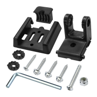
Connect ratchets to transducer knuckle and fit pivot arm, loosely installing pivot bolt.

Mounting and Adjusting Transducer Assembly

Mount assembly, adjust angle and vertical position for optimal water contact and levelness.

Routing the Cable

Cable Routing Methods

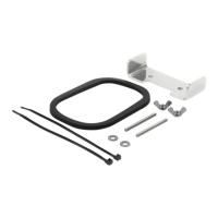
Route cable over transom or through a hole above waterline, avoiding interference sources.

Securing the Cable

Use cable clips and clamps, securing with screws and marine-grade silicone sealant.

Connecting the Cable

Transducer Port Connection

Connect transducer cable to the control head port and secure the connection.

Testing and Finishing the Installation

Initial Testing and Speed Adjustment

Test sonar view at low speeds, then gradually increase speed, adjusting transducer if needed.

Finalizing Mounting and Drilling

Drill third mounting hole, tighten screws, and ensure transducer is level and submerged.

Locking Down the Transducer (Optional)

Securing the Kick-Up Bracket

Option to lock the two-piece kick-up bracket to prevent it from kicking up.

Finalizing Optional Lock Mechanism

Drill fourth hole and install screw to lock the pivot arm into place.

Setting Up the Transducer on the Control Head

Transducer Selection Procedure

Navigate menus to select the correct transducer type for system operation.

Maintenance

Cleaning and Care

Periodically clean transducer face with mild soap to remove marine growth or air bubbles.

1-Year Limited Warranty

Warranty Terms and Exclusions

Details Humminbird's one-year warranty, including coverage, limitations, and exclusions.

Humminbird Service Policy

Repair and Service Information

Information on factory repair turnaround, service charges, and warranty after repair.

Returning Your Unit for Service

In-Warranty Service Procedures

Steps for obtaining a Repair Authorization Number and returning unit for in-warranty service.

Out-of-Warranty Service Procedures

Steps for obtaining a Repair Authorization Number and returning unit for out-of-warranty service.

Contact Humminbird

Contact Information

Provides Humminbird's web site, email address, and telephone number for support.

Important Warnings and Compliance

Safety and Operational Warnings

Key warnings regarding product use, installation, and potential hazards.

Environmental Compliance Statement

Information on WEEE Directive and responsible disposal of electronic equipment.

Related product manuals