EasyManua.ls Logo

Hunter 44665 User Manual

Hunter 44665
2 pages
To Next Page IconTo Next Page
Page #1 background imageLoading...
Page #1 background image
Ch
T E M P
Form No. 44004-01 R030409
Your Model 44668/44665 thermostat
can read the temperature from up to
three weather-resistant sensors at a
distance of up to 75 feet.
Note: Distance my vary based on
building construction or other interfering
frequencies.
You can control the temperature from
one indoor sensor and/or thermostat,
with the second and third being a sensor
only. If you use multiple sensors, you
might want to number them. Simply use
a marker to write a number on the back
of each sensor. The remote sensors are
designed to either be mounted on a wall,
or set on a desk or side table.
Consult the Thermostat Instruction
Manual for instructions in setting the
thermostat to accommodate the remote
sensors.
You may also download directly from
Hunter Fan Company at www.hunterfan.
com/support.
1. Remove the four screws on the back
of the Remote Sensor. See Figure 1. The
Outer Cover will drop off.
2. Remove the Battery Compartment
Cover, which is underneath the Outer
Cover. See Figure 2.
Figure 1.
Outer Cover
4. Install two fresh AA alkaline batteries
into the Battery Compartment, being
careful to observe the battery polarities.
See Figure 4.
Figure 2.
Battery
Cover
3. Use the tip of a paper clip to set
the FIRST FOUR Remote Sensor DIP
Switches to any conguration you desire.
NOTE: Each sensor you use must have a
different setting. See Figure 3.
To set the remote sensor to display the
temperature in Fahrenheit, place the
FIFTH DIP switch in the DOWN position.
To set the remote sensor to display the
temperature in Celsius, place the FIFTH
DIP switch in the UP position.
Battery
Compartment
(Batteries
installed)
Figure 4.
1. When the batteries are installed, the
LCD Display will show the rst initializing
screen for approx. 2 seconds. See Figure
5.
2. The LCD Display will then show the
second initializing screen for approx. 10
seconds. See Figure 6.
Ch
R H T E M P
C
%
Figure 5.
Ch
Figure 6.
Figure 3.
ON
DIP
1
2 3
4
5
Model 44758 Remote Sensor
Owners Manual
Setup
InItIal Start-up
3. The LCD Display will then show the
normal operating screen. See Figure 7.
NOTE: It may take up to 30 seconds for
the thermostat to "pick-up" the sensor.
Ch
T E M P
Figure 7.
Channel
4. The Remote Sensor Screen will
display the ambient temperature and, in
the bottom-left corner, a channel number
between 0 and 15. See Figure 7. This
will be the channel to which you will set
the thermostat to read the Remote Sensor.
See the Thermostat Instruction Manual,
page 14, Option 8.
5) Place the Battery Compartment Cover
over the Battery Compartment.
Wall MountIng
1. Replace the Outer Cover as shown in
Figure 8. Use the four screws to secure
the Outer Cover.
Question and Answer IconNeed help?

Do you have a question about the Hunter 44665 and is the answer not in the manual?

Hunter 44665 Specifications

General IconGeneral
Accuracy±1°F
DisplayDigital
Control TypeProgrammable
MountingWall Mount
Power SourceBattery

Summary

SETUP

Removing the Outer Cover

Step-by-step guide to remove the outer casing of the remote sensor.

Accessing Battery Compartment

Instructions for removing the battery compartment cover.

Configuring DIP Switches

Guide to setting DIP switches for desired sensor configuration and temperature units.

Installing Batteries

Procedure for correctly installing AA alkaline batteries into the remote sensor.

Securing Battery Compartment

Steps to close and secure the battery compartment cover.

INITIAL START-UP

First Initialization Screen

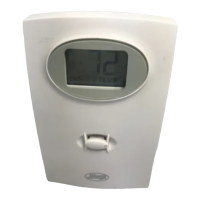
Description of the initial display shown upon battery installation.

Second Initialization Screen

Details of the second screen displayed during the sensor's startup process.

Normal Operating Screen

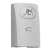
Explanation of the standard display shown once the sensor is operational.

Remote Sensor Display Details

Information about what the remote sensor screen shows, including temperature and channel.

WALL MOUNTING

Securing Outer Cover

Instructions to reattach and secure the outer cover after mounting preparation.

Mounting on a Wall

Guidance on using a screw to mount the remote sensor onto a vertical surface.

TO STAND ON A SURFACE

Securing Outer Cover for Surface Placement

Steps to attach the outer cover for placing the sensor on a flat surface.

Surface Placement

Instructions for positioning the remote sensor on a horizontal surface.

TEMPERATURE INDICATION

Celsius Temperature Display

Explanation of the °C indication next to the temperature on the display.

Temperature Measurement Range

Details on the sensor's temperature range and 'HI'/'LO' indicators.

Low Battery Indication

Description of the flashing indicator for a low battery.

Depleted Battery Indication

Information on the display when the battery is depleted and sensor has ceased functioning.

TROUBLESHOOTING

Troubleshooting: Blank LCD

Solutions for when the remote sensor's LCD display is blank.

Troubleshooting: Temperature Mismatch

Solutions for when the thermostat and sensor show different temperatures.

TECHNICAL SPECIFICATIONS

Related product manuals