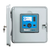
ACC2 DECODER PROGRAM INFORMATION
PROGRAMMING DECODERS
Insert the decoder’s red and blue wires in the Programming Port holes (inside controller
cabinet). It does not matter which color wire goes in which hole.
Dial to Decoder menu and select Program Decoder.
Leave the Location checked for Programming Port, and press the so key for Read Decoder.
Enter the Station numbers (or press Pump decoder or Sensor decoder) and enter other
information as needed. Press Program Decoder.
When display reads Decoder Programming Successful!, remove wires and install decoder.
If programming fails, reinsert wires rmly and repeat.
It is also possible to re-program an installed decoder via the two-wire path. Check the
Decoder Location box for Two-Wire Path, and enter the station number to re-program.
Then repeat the steps above.
VIEW CONFIGURATION/VIEW STATUS
Enter any decoder address to view details of any decoder installed in the two-wire path.
Station Assignments
Each A2C-D75 output module enables up to 75 stations. You can assign station numbers
from one module to another, if needed, for longer wire paths.
Set the upper and lower limits for the stations assigned to each module, to rearrange the
stations as needed.
Decoder Diagnostics
View the current draw and status for each decoder output module.
Station Finder: Press this button to help nd a decoder in the eld. Enter a station number
to chatter the solenoid on the valve for up to 30 minutes, so that the station can located by
listening in the eld
Wire Test: Press this button to put a 60 Hz current on the two-wire path, so that a clamp
meter can be used to detect faults to earth.
Decoder Inventory
Press Refresh Inventory to collect data on all available stations. This will take a few minutes.
Data is shown for one decoder output module at a time. Press Next Module to see the results
for each output module.
Stations with a low “Comm %” may have connection issues.
Update Available shows whether any decoders may need to be updated. If all stations are
“No,” then all stations are up to date.
Update Decoders
New controller updates may include new versions of decoder rmware.
If decoders in the Inventory show “Yes” in the Update Available? column, press Update
Decoders to send the latest rmware to all decoders in the system. This may take up to 20
minutes.
Output Module Lights
Each A2C-D75 output module has 4 status LED lights.
Decoder Fault
Red = Station overload
Communicating
Green: Two-wire communications
Amber = Programming,
wire test mode
Activity
Red = Line overload
Green = Station active
Line Status
Green (solid) = Line is OK
Green (blinking) = Output
module damaged
Blue is PMS 308C
Icons are white
Cyan outline is the dieline and
does not print
White circles are translucent
 Loading...