41605-01 03/08/2003 4 © 2003 Hunter Fan Company
Step 9: Installing Light Fixture
Warning:
• To avoid possible electrical shock, before installing
light fixtures, disconnect power by turning off the
circuit breakers both to the outlet box and to its as-
sociated wall switch location. If you cannot lock the
circuit breakers in the off position, securely fasten a
prominent warning device, such as a tag, to the ser-
vice panel.
• Connect house wiring to the fan before attaching
the light fixture to the fan.
• All wiring must be in accordance with national and
local electrical codes and ANSI/NFPA 70. If you are
unfamiliar with wiring, you should use a qualified elec-
trician.
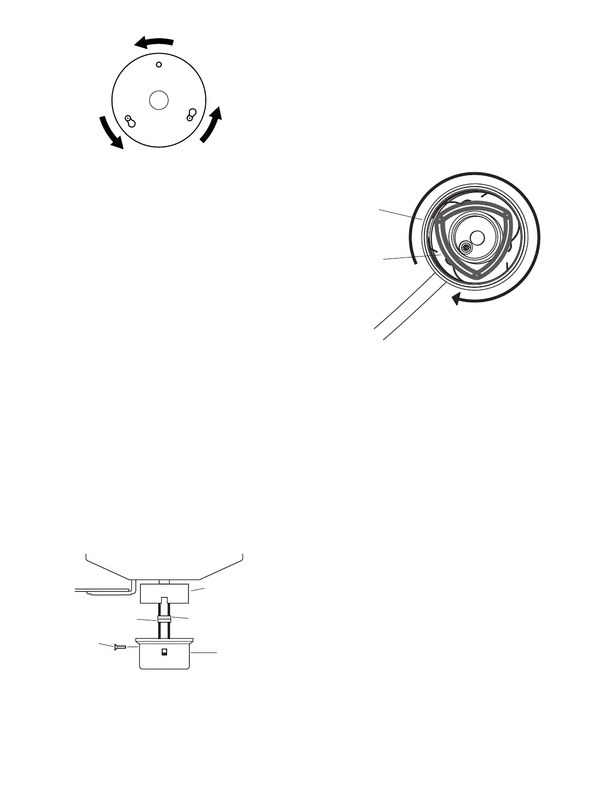
A. Connect the upper plug connector from the motor to
the lower plug connector in the lower switch housing
assembly. See Figure 14.
Note: Both plug connectors are polarized and will only fit
together one way. Make sure that both connectors are prop-
erly aligned before connecting them together. Incorrect
connection could cause improper operation and damage
to the product.
B. Place the lower switch housing assembly over the up-
per switch housing. Align the side screw holes in the
upper and lower switch housings. Attach the lower
switch housing to the upper switch housing with three
#6-32 x 3/8" housing assembly screws. See Figure
14.
Figure 13
Figure 14
Installing the Easy Lock
TM
Glass Shades
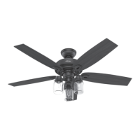
A. Insert the glass shade into the cup around the bulb
socket as shown in Figure 15.
B. While holding the fitter with one hand, twist the glass
shade clockwise to lock in place.
C. Install three max 60 Watt medium base incandes-
cent bulbs.
NOTE: To remove the glass shade, first remove
the bulb then twist the shade counterclockwise.
Installing Lower Cover Without Light Fixture
A. Connect the upper plug connector from the motor to
the lower plug connector in the lower switch hous-
ing assembly. See Figure 14.
Note: Both plug connectors are polarized and will only fit
together one way. Make sure that both connectors are
properly aligned before connecting them together. Incor-
rect connection could cause improper operation and dam-
age to the product.
B. Place the lower switch housing assembly over the
upper switch housing. Align the side screw holes in
the upper and lower switch housings. Attach the
lower switch housing to the upper switch housing
with three #6-32 x 3/8" housing assembly screws.
See Figure 14.
Lower Plug
Connector
Upper Switch
Housing
Upper Plug
Connector
Lower
Switch
Housing
Housing
Assembly
Screw
Figure 15
Cup
Neck of
Glass Shade