Do you have a question about the Hunter Low Profile and is the answer not in the manual?
Choose location, checking for blade clearance and site requirements.
Notes on included hardware and necessary purchases like outlet boxes and wire nuts.
Ensure blades are 7' from floor and 24" from obstructions for efficiency.
Carefully unpack to prevent damage to fan parts.
Inspect motor assembly and blades for damage; keep sets together.
Confirm all parts are present, especially the bag of parts.
Mount metallic outlet box to a 2x4 cross brace between joists using wood screws.
Thread wires through ceiling plate and attach to 2x4 brace using wood screws.
Hang motor by placing hooks into support loops on ceiling plate.
Connect supply leads to motor leads using approved connectors.
Spread wires apart in box, turn splices upward, and push into outlet box.
Secure motor cover to ceiling plate using 8-32 screws.
Attach wood blades to blade brackets using screws, inserting grommets if needed.
Align blade holes with hub, using screws to secure blade brackets.
Use provided kit to correct fan wobble during operation.
Partially install housing screws into the mounting plate.
Thread the upper plug connector through the center opening of the housing.
Align slots, turn housing counterclockwise, and tighten screws securely.
Connect upper plug from motor to lower plug in switch housing assembly.
Place lower housing over upper, align holes, and secure with screws.
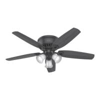
Insert glass shade into the cup around the bulb socket.
Twist glass shade clockwise to lock it in place.
Install three max 60 Watt medium base incandescent bulbs.
Connect upper plug from motor to lower plug in switch housing assembly.
Place lower housing over upper, align holes, and secure with screws.
Operate fan through sequence: high, medium, low, off using pull chain.
Electrically reversible motor; switch direction by toggling reversing switch.
Check power, wiring connections, switches, and shipping blocks.
Tighten loose screws, check for cracked blades or non-approved speed controls.
Balance blades, check ceiling clearance, tighten screws, and secure assembly.
| Fan Type | Ceiling Fan |
|---|---|
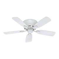
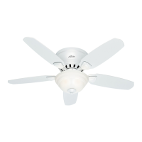
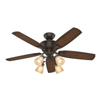
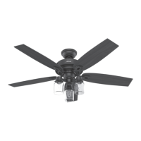
| Style | Low Profile |
| Mounting | Flush Mount |
| Reversible Motor | Yes |
| Warranty | Lifetime |