6-
29
Active Testing of a SCR
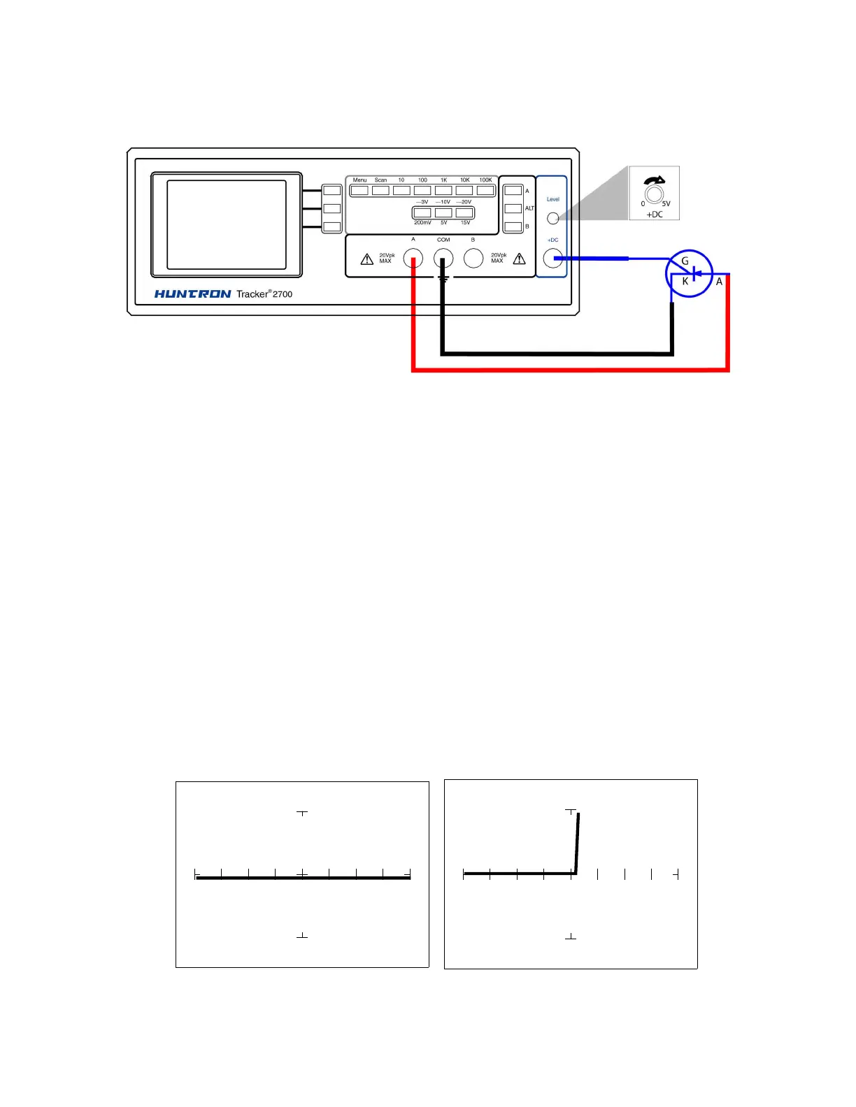
Connect the SCR to the Tracker 2700 as illustrated below:
Figure 6-39. DC Source Test Circuit for a SCR
Do the following to dynamically test a SCR using the Tracker 2700:
1. Select the 10V, 1 kΩ
ΩΩ
Ω range.
2. Set the frequency to 60 Hz.
3. Connect the blue easy grabber from Tracker 2700's DC Source +DC output terminal to the
component's gate lead.
4. Connect the red test probe from Tracker 2700's A test terminal to the SCR's anode lead.
5. Connect the black test probe from Tracker 2700's Common test terminal to the SCR's
cathode lead.
6. Turn the DC Level knob clockwise to increase the voltage level from 0 VDC.
DC Level = 0V DC Level = 5V