7-
4
Comparing Two TTL Families
Although the logic function is the same, there are differences in the circuitry of each logic family.
These differences can be readily seen in their signatures using the Tracker 2700.
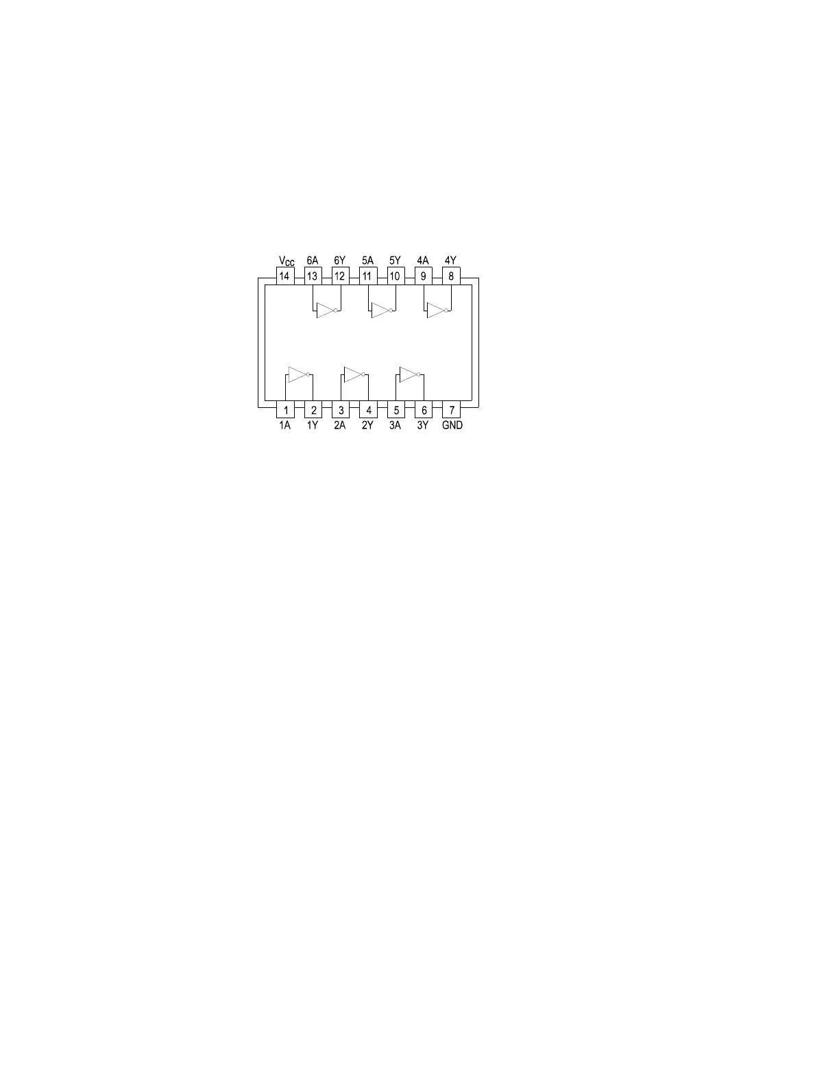
We will illustrate these concepts with the following example of two hex inverters, a 7404 and a
74LS04 from different logic families. From the logic diagram below, you can see that they have
the same logic functions and pin order. The difference is that the LS chip uses Schottky
transistors in its internal construction for increased performance and reduced power consumption.
Note that there are only four types of circuit connections and therefore only four signatures on this
chip: inverter inputs, inverter outputs, V
CC
and ground.
Figure 7-3. Diagram Of 7404 & 74LS04