7-
5
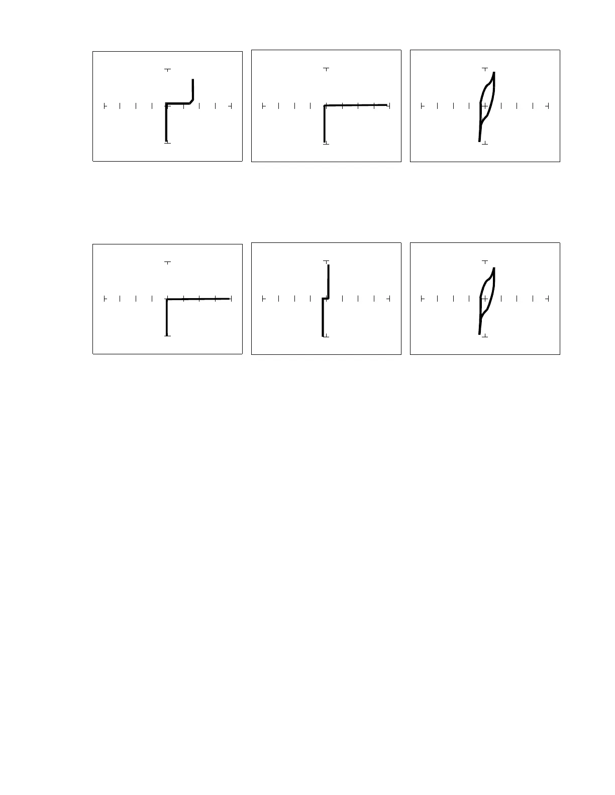
Pin 1 input - 15V,10 kΩ
ΩΩ
Ω Pin 2 output - 15V,10 kΩ
ΩΩ
Ω Pin 14 power - 10V, 100Ω
ΩΩ
Ω
Figure 7-4. Signatures Of A 7404 Hex Inverter. Common To Pin 7(Gnd)
Pin 1 input - 15V,10 kΩ
ΩΩ
Ω Pin 2 output - 15V,10 kΩ
ΩΩ
Ω Pin 14 power - 10V,100Ω
ΩΩ
Ω
Figure 7-5. Signatures Of A 74LS04 Hex Inverter. Common To Pin 7 (Gnd)
Note the differences between the two logic families. They have the same logic function but
different construction, therefore different signatures. To test one of these chips without another
reference chip available just compare each input's signature with the other five inputs. Similarly,
compare each output's signature with the other five outputs.