7-
6
CMOS Logic Family
CMOS circuits are constructed differently than TTL circuits. The inputs to CMOS transistors are
capacitive due to the use of field-effect transistors (FET) instead of bipolar transistors used in
TTL.
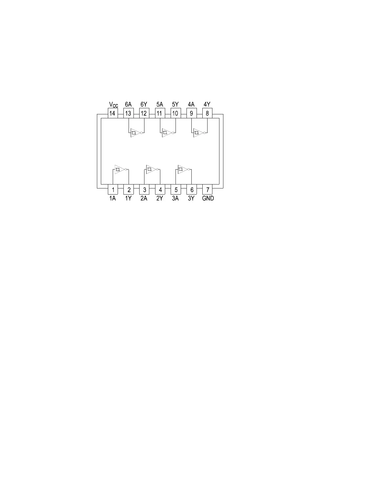
In this example, we will choose a 74HC14 Schmidt Trigger Hex Inverter. The HC designation
means that it's a member of the high-speed CMOS logic family. From the block diagram of this
part, you can see that it has only four different circuit functions. They are inverter input, inverter
output, power supply V
CC
input, and power supply ground.
Figure 7-6. Diagram Of 74HC14
1. Select the 10V, 100Ω
ΩΩ
Ω Range.
2. Set the test signal frequency to 60 Hz.
3. Place or clip the black test lead from the Tracker 2700's Common terminal to the IC's ground
pin. For this example, the ground pin of the 74HC14 is pin 7.
4. Use the red test lead from the Tracker 2700's A test terminal and probe each pin of the IC.
For this example, pins 1, 3, 5, 9, 11, and 13 are all input buffer circuits so they will have
identical signatures. (Note: This is only for ICs out of circuit.)
5. Similarly, use the red test lead and probe the output buffer pins 2, 4, 6, 8, 10, and 12. These
pins will have the same signatures. (Note: This is only for ICs out of circuit.)
6. Use the red test lead from the Tracker 2700's A test terminal and probe the power supply V
CC
input pin. For this example, the V
CC
pin of the 74HC14 is pin 14.
 Loading...