7-
7
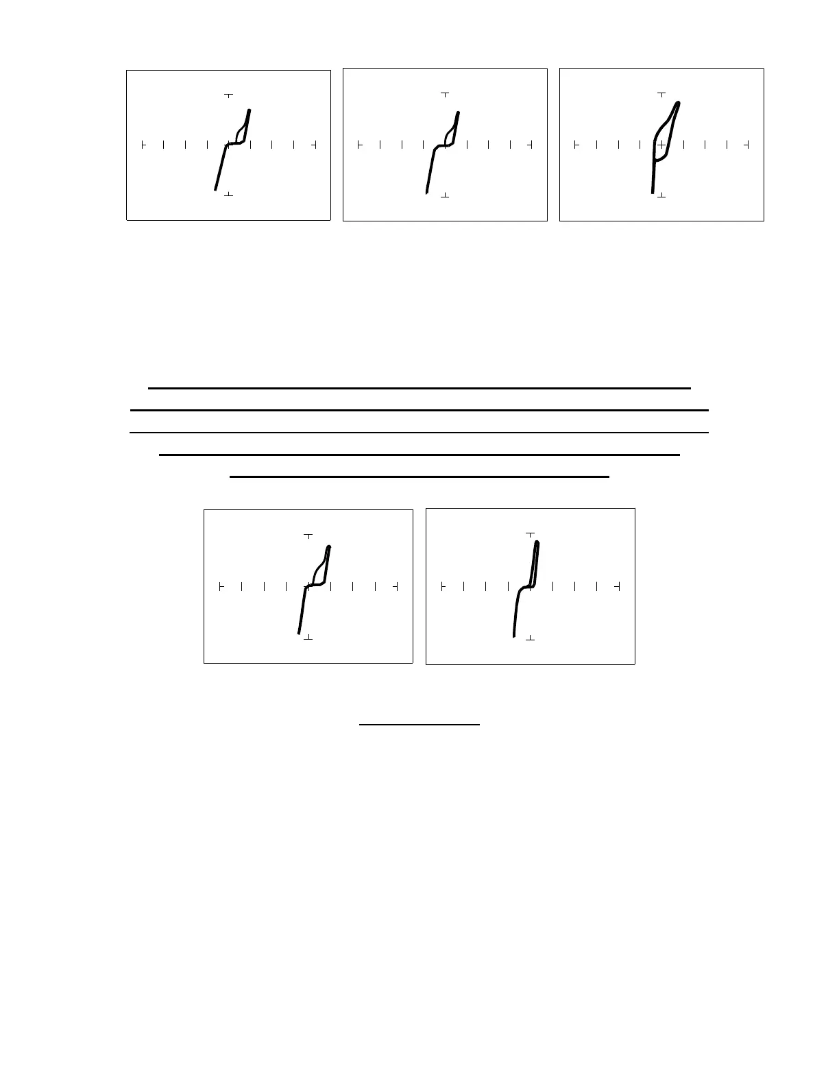
Pin 1 Input - 10V,100Ω
ΩΩ
Ω Pin 2 Output - 10V,100Ω
ΩΩ
Ω Pin 14 V
CC
- 10V,100Ω
ΩΩ
Ω
Figure 7-7. Signatures Of A 74HC14 CMOS Hex Inverter. Common to Pin 7(GND)
CMOS Components And Test Signal Frequency F
s
CMOS logic circuits inherently have a significant amount of
internal capacitance. This junction capacitance is visible in the
CMOS signatures when using the Tracker 2700. Capacitance in
CMOS circuitry may be emphasized or de-emphasized by
changing the frequency of the test signal.
F
S
= 20 Hz F
S
= 200 Hz
10V, 1 KΩ
ΩΩ
Ω Range
Figure 7-8. Signatures Of A 74HC14 Input Pin At Different Frequencies