7-
12
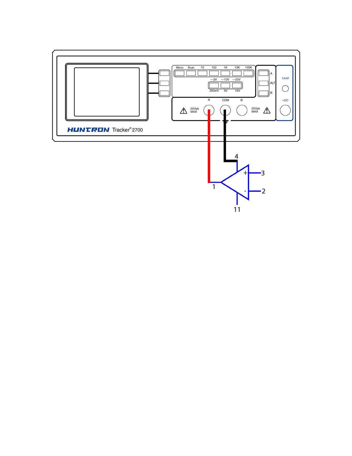
Op Amp Signatures
Figure 7-11. Tracker 2700 With Test Leads To An Op Amp
Do the following to display the Tracker signatures of an op amp:
1. Select the 15V, 1 kΩ
ΩΩ
Ω range.
2. Set the test signal frequency to 60 Hz.
3. Place or clip the black test lead from the Tracker 2700's Common terminal to the IC's ground
or a power supply pin. For this example, the negative power supply pin of the 741 is pin 4
and the positive power supply is pin 11.
4. Use the red test lead from the Tracker 2700's A test terminal and probe each pin of the IC.
5. Observe that the signature of each of the op amp's pins are unique.