1-
8
Internal Signal Fuses
The Tracker 2700 has two internal signal fuses. Make sure the Tracker 2700 is turned off and the
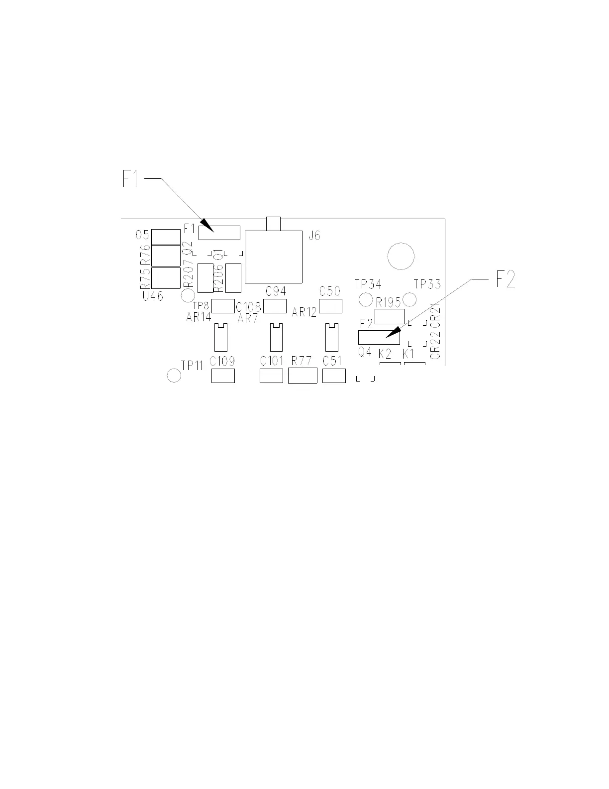
power cord is disconnected before opening the case. The fuses are located in the back right hand
corner of the Tracker 2700 as shown below.
Figure 1-2. Internal Signal Fuse Locations
Note: There can be two styles of fuses used at these locations. Older units will have the fast blow
Wickman style fuses (red in color that mount into sockets). Newer units will have surface
mounted, self-resetting type fuses that are directly soldered onto the PCB. Self-resetting fuses
don’t need to be replaced. When the fault condition is removed, these fuses will reset to the
normal operating condition. The resistance of these fuses increases dramatically when a fault
condition occurs causing no current to flow through the probes. For example, probing charged
capacitors may blow the fast blow fuses and you will see no trace on the LCD. The self-resetting
fuse restricts the current flow and you will see either no signature or a vertical line moved to either
side of the LCD. If you remove the probes from the charged capacitor, the open circuit horizontal
trace will return after a recovery time of a few seconds. If the system does not recover, you may
need to power off and wait a few seconds before powering up again.
If you have the older style Wickman fuses and wish to replace them with self-resetting fuses,
there is a Fuse Replacement Kit (p/n 98-0417) available from Huntron. Please read the
instruction sheet that is included in the kit.
The new self-resetting fuse at F1 is 30V, 100mA Raychem p/n MICROSMD010-2, and the fuse
at F2 is a 30V 50mA Raychem p/n MICROSMD005-2. Both these fuses are included in the Fuse
Replacement Kit.
 Loading...