2-
6
2-10. Channel Selection
There are two channels on the Tracker 2700 (channel A and channel B) which are selected by
pressing the appropriate front panel button. When using a single channel, the red probe should
be plugged into the corresponding channel test terminal and the black probe or common test lead
should be plugged into the common test terminal. When testing, the red probe should be
connected to the positive terminal of a device (i.e. anode, +V, etc.) and the black probe should be
connected to the negative terminal of a device or a common reference (i.e. cathode, ground).
Following this procedure should assure that the signature appears in the correct quadrants of the
LCD display.
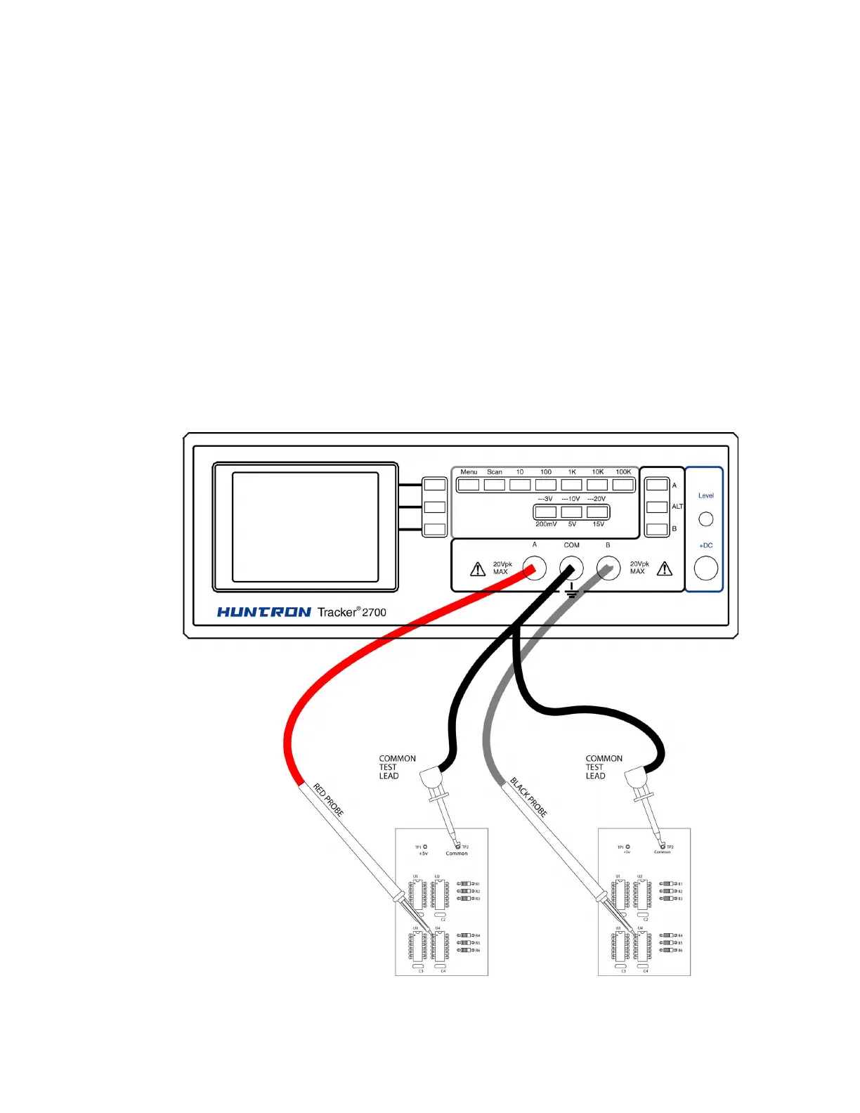
2-11. Alternate Mode
The Alternate mode of the Tracker 2700 is provided to automatically switch back and forth
between channel A and channel B. This allows easy comparison between two devices or the
same points on two circuit boards. The Alternate mode is selected by pressing the ALT button on
the front panel, and the alternation frequency is varied by pressing the rate control button on the
Startup screen until the desired alternation frequency is reached. The RATE is numbered from 1
to 9. This number indicates the number of times the signature will be updated before changing to
the next channel. Figure 2-4 shows how the instrument is connected to a known good board and
a board under test. This test mode uses the supplied common test leads to connect two
equivalent points on the boards to the common test terminal. Note that the black probe is
plugged into the channel B test terminal.
 Loading...