3-
4
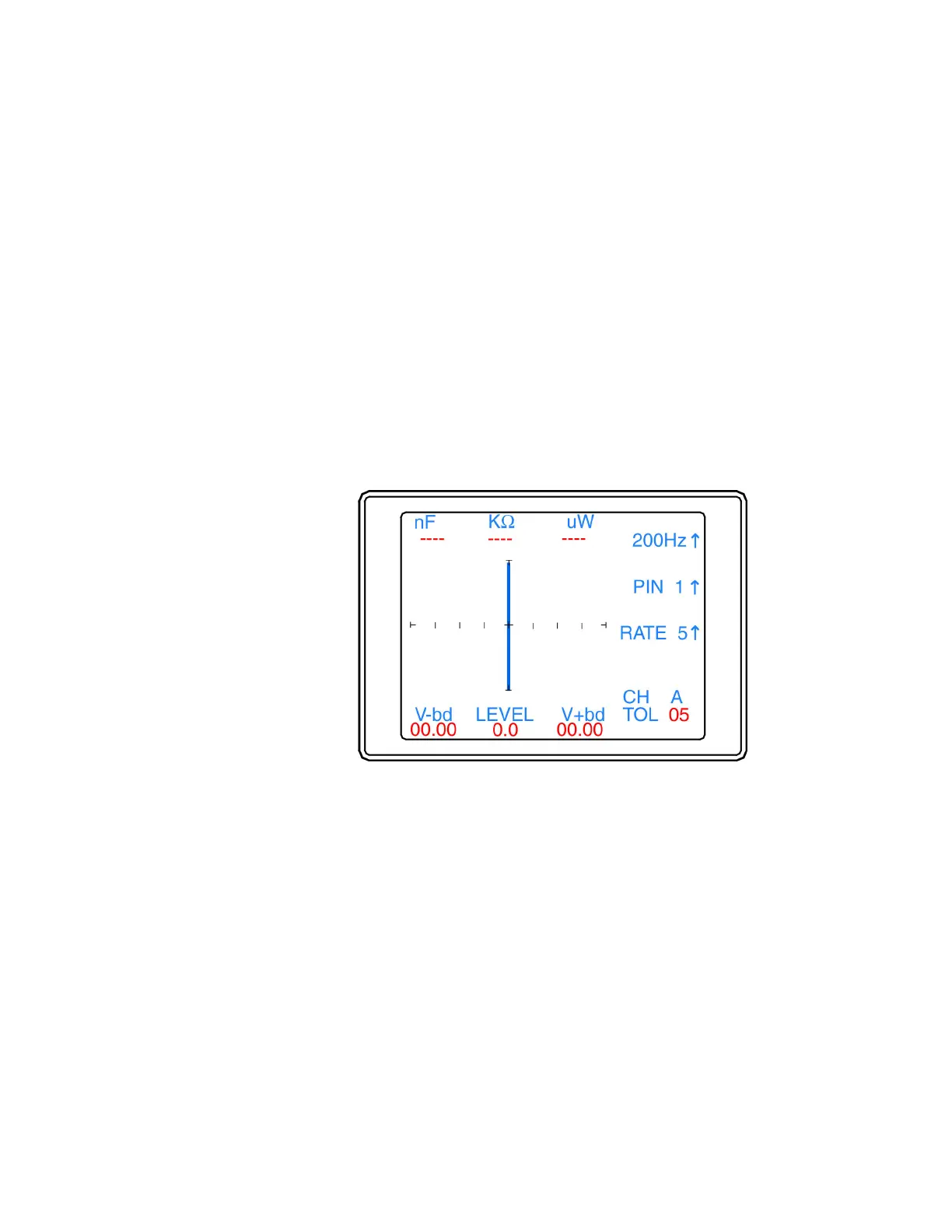
Figure 3-4. Tracker 2700 LCD Display with Open Test Terminals.
3-4. Vertical Axis
The amount of vertical trace deflection on the LCD display is controlled by the voltage dropped
across the internal impedance R
s
of the Tracker 2700. Because R
s
is in series with the load R
L
,
this voltage will be proportional to the current flowing through R
L
. This current that flows through
the component under test is the vertical part of the Tracker signature.
When the R
L
is zero ohms (0 Ω) as when you short an output terminal to the common terminal,
there is no voltage dropped across R
L
, so there is no horizontal component in the Tracker
signature. This short circuit signature is a vertical line trace on the LCD display.
Connect the red microprobe to the output channel A jack on the Tracker 2700 and the black
microprobe to the Common jack.
1. Touch and hold the probes together and observe the Tracker signature on the LCD display.
2. You will see a vertical line trace in the middle of the LCD display.
Figure 3-5. LCD Display With Vertical Axis, Graticule Lines displaying
a short circuit.
 Loading...