3-
7
conductance signatures can show conduction in both forward and reverse-bias. This will form a
zener semiconductor pattern which will show both junctions.
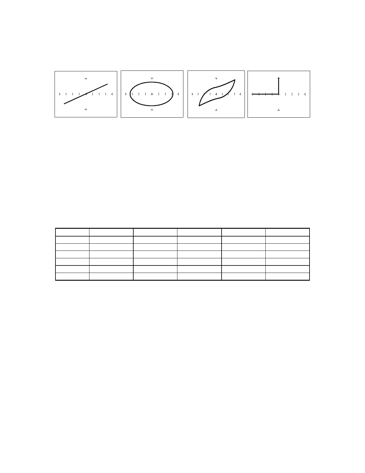
RESISTOR CAPACITOR INDUCTOR SEMICONDUCTOR
Figure 3-10. Tracker Signatures of 4 Basic Components.
3-7. Smart Tracker Active Range (STAR) feature.
The Tracker 2700 has a built-in operating feature called STAR (Smart Tracker Active Range).
This important feature protects sensitive components from possible exposure to excessive power
(for example, 15V and 10Ω).
The table below specifies the active and disabled voltage & resistance test range combinations.
10Ω 100Ω 1kΩ 10kΩ 100kΩ
200mV
Enabled Enabled Enabled Enabled Enabled
3 V Disabled
Enabled Enabled Enabled Enabled
5 V Disabled
Enabled Enabled Enabled Enabled
10 V Disabled
Enabled Enabled Enabled Enabled
15 V Disabled Disabled
Enabled Enabled Enabled
20 V Disabled Disabled Disabled Disabled
Enabled
Table 3-1. Valid Tracker 2700 Ranges (STAR)
To illustrate the STAR feature, do the following:
1. Select the 200mV, 10Ω range. This is a valid range shown by the LEDs being illuminated on
the 200mV and 10Ω buttons.
2. Press the 5V button. Notice that the 5V LED is on and the resistance range changes to 100Ω
automatically. The 5V, 10Ω range is disabled.
3. Now press the 15V button. Notice that the 1kΩ resistance is automatically selected. The 15V,
100Ω range is disabled and the next valid resistance range was activated at the selected
voltage.
4. 20V only allows 100kΩ to be used.
 Loading...