5-
17
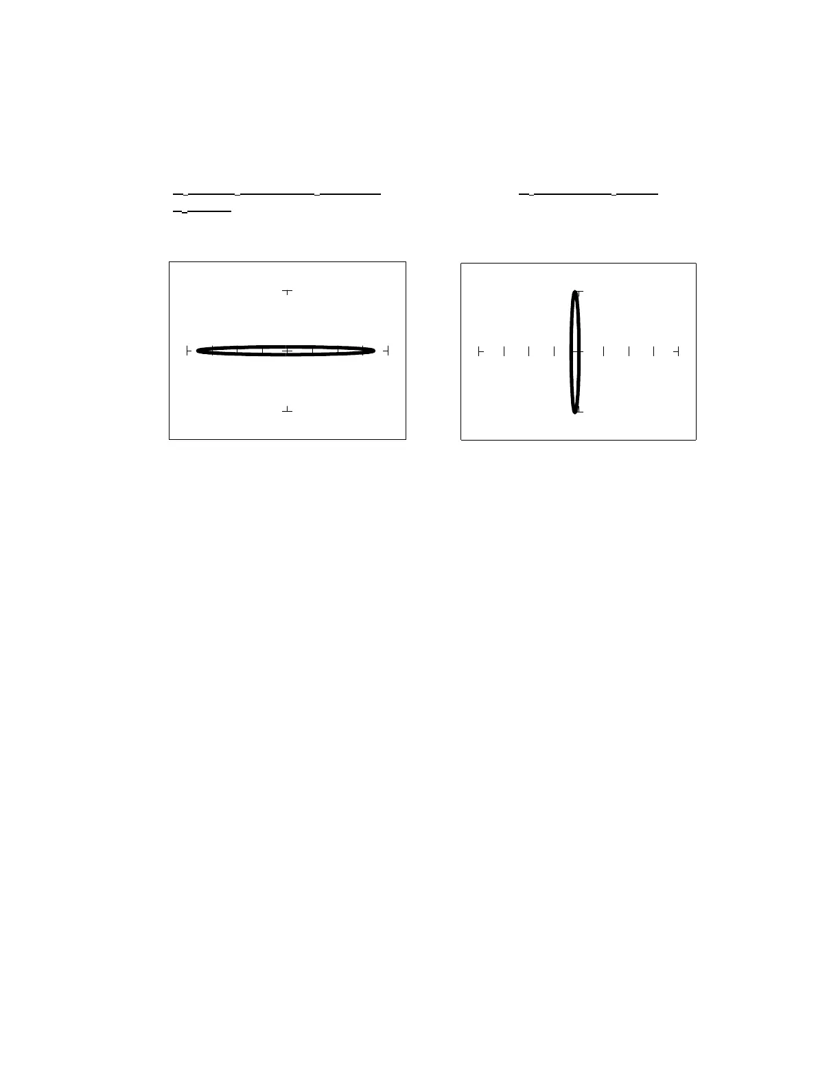
Minimum and Maximum Capacitor Values
Because of the flexibility of the Tracker 2700 range selection, a wide range of capacitive values
can be tested. Usable signatures can be obtained from very large or very small capacitors as
shown in figures 5.21.
Capacitance = 10pF Capacitance=16000µ
µµ
µF
V
s
=3V, R
s
=100KΩ
ΩΩ
Ω, F
s
=2000Hz V
s
=200mV, R
s
=10Ω
ΩΩ
Ω,
F
s
=20Hz
Fig 5.21 Minimum and Maximum Capacitance that will Display a Loop Type Signature
Note: Be sure to discharge large capacitors before testing to avoid damaging the Tracker 2700.
Capacitor Failures - Leakage
One common physical failure in capacitors is dielectric leakage. The dielectric or insulator in a
capacitor normally acts as a non conductor between the capacitor's two plates. A flawed
capacitor develops a conductive or leakage path between its two plates. This can be thought of
as a resistance in parallel with the capacitance when observing its tracker signature. The
following examples show what some capacitor leakage problems may look like on the Tracker
2700 display.
 Loading...