5-
18
Normal Capacitor Leaky Capacitor
10V, 100Ω
ΩΩ
Ω Range, F
S
= 60 Hz
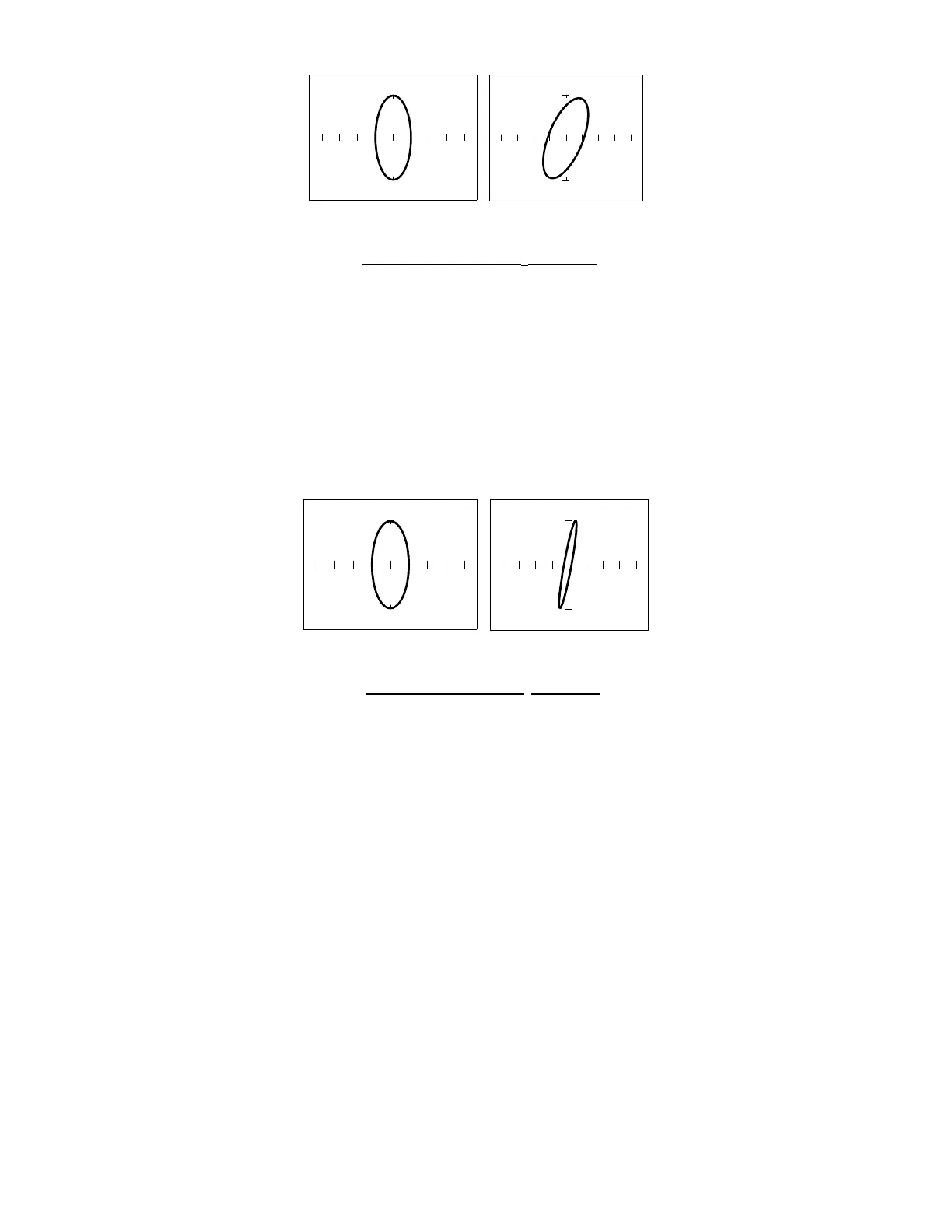
Figure 5-22. Signatures of a 100 µF Capacitor with Dielectric Leakage
This example only simulates the leakage flaw by adding a 100 Ω resistor in parallel to a 100 µF
capacitor. It shows the signature change from a normal circular ellipse pattern to a sloped and
depressed vertical pattern. The signature of a real capacitive leakage would be quite similar to
this example.
Another example of capacitive leakage is shown for a 10 µF capacitor.
Normal Capacitor Leaky Capacitor
10V, 100Ω
ΩΩ
Ω Range, F
S
= 60 Hz
Figure 5-23. Signatures of a 10 µF Capacitor with Dielectric Leakage
Again, this example only simulates the leakage flaw by adding a 68 Ω resistor in parallel to a 10
µF capacitor. It shows the signature change from a normal circular ellipse pattern to a sloped
and depressed vertical pattern. The signature of a real capacitive leakage would be quite similar
to this example.
As you can see from the two previous examples, adding resistance in parallel to a capacitor
distorts the normal signature with a diagonal bend to it. This is our first look at a composite
signature, the kind of signature the Tracker 2700 displays when there are several components
connected together in a circuit.
Review
 Loading...