5-
23
Understanding Inductive Signatures
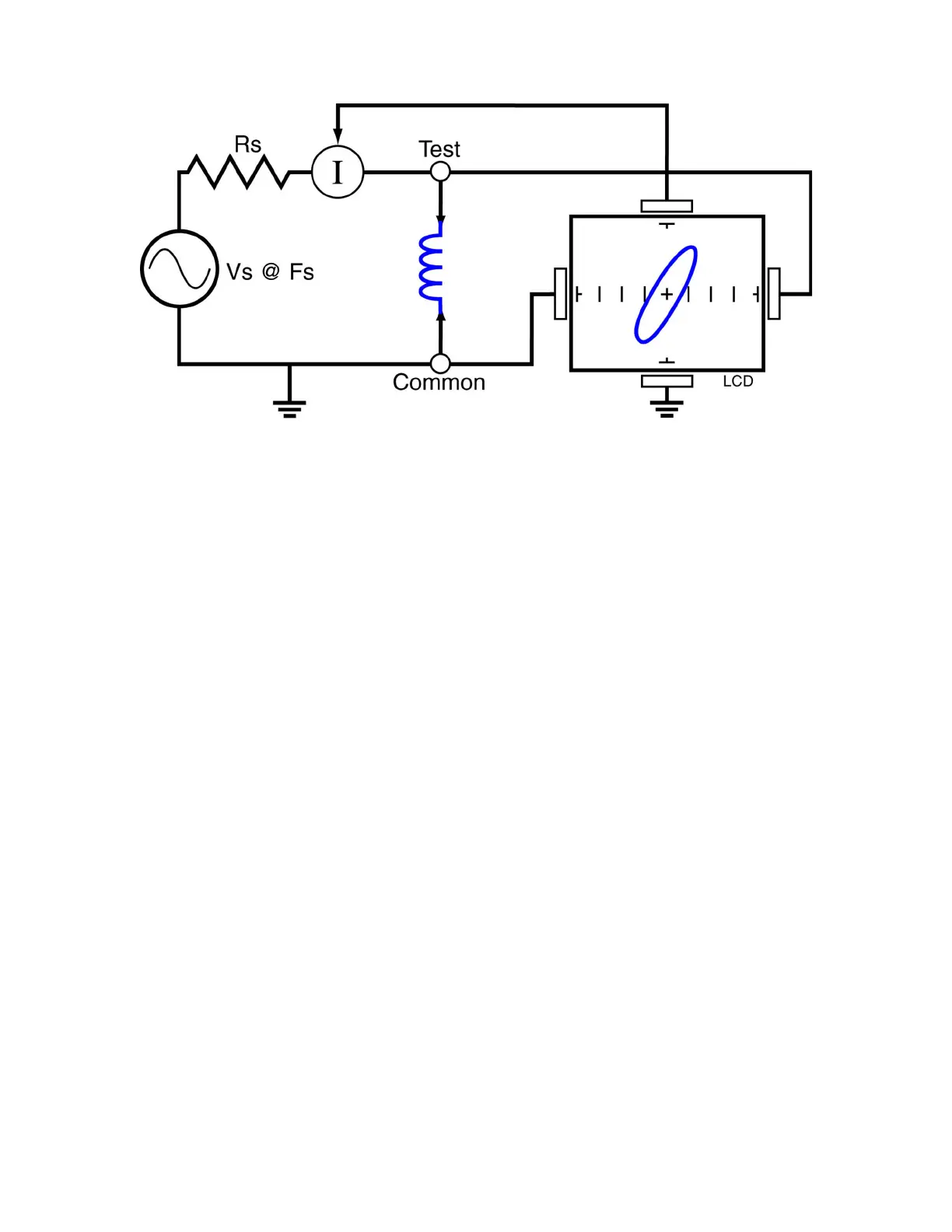
Figure 5-28. Tracker Core Circuit Block Diagram with an Inductor
The Tracker 2700's block diagram shows an inductor between the test terminals. The current is
represented by the vertical axis and is derived as a series current that flows through Tracker
2700’s internal resistance, R
S.
The voltage is represented by the horizontal axis and is derived as
a voltage across the inductor.
The formula for the reactance X
L
of an inductor is:
X
L
= 2πfL
As the test signal frequency increases, the inductive reactance X
L
becomes larger. As a result,
the inductor’s Tracker signature will change from a rounder elliptical to a flatter resistive type
pattern. The size and shape of the ellipse depend on the inductor value, test signal frequency,
and the selected resistance R
S
.
Since inductors in reality are not pure inductors, the elliptical signatures they form on the Tracker
2700 display usually are distorted. Inductors constructed with a ferrite core make the inductive
characteristics different from those constructed without. The Tracker 2700 responds with a unique
Tracker signature for each inductor type.
 Loading...