5-
22
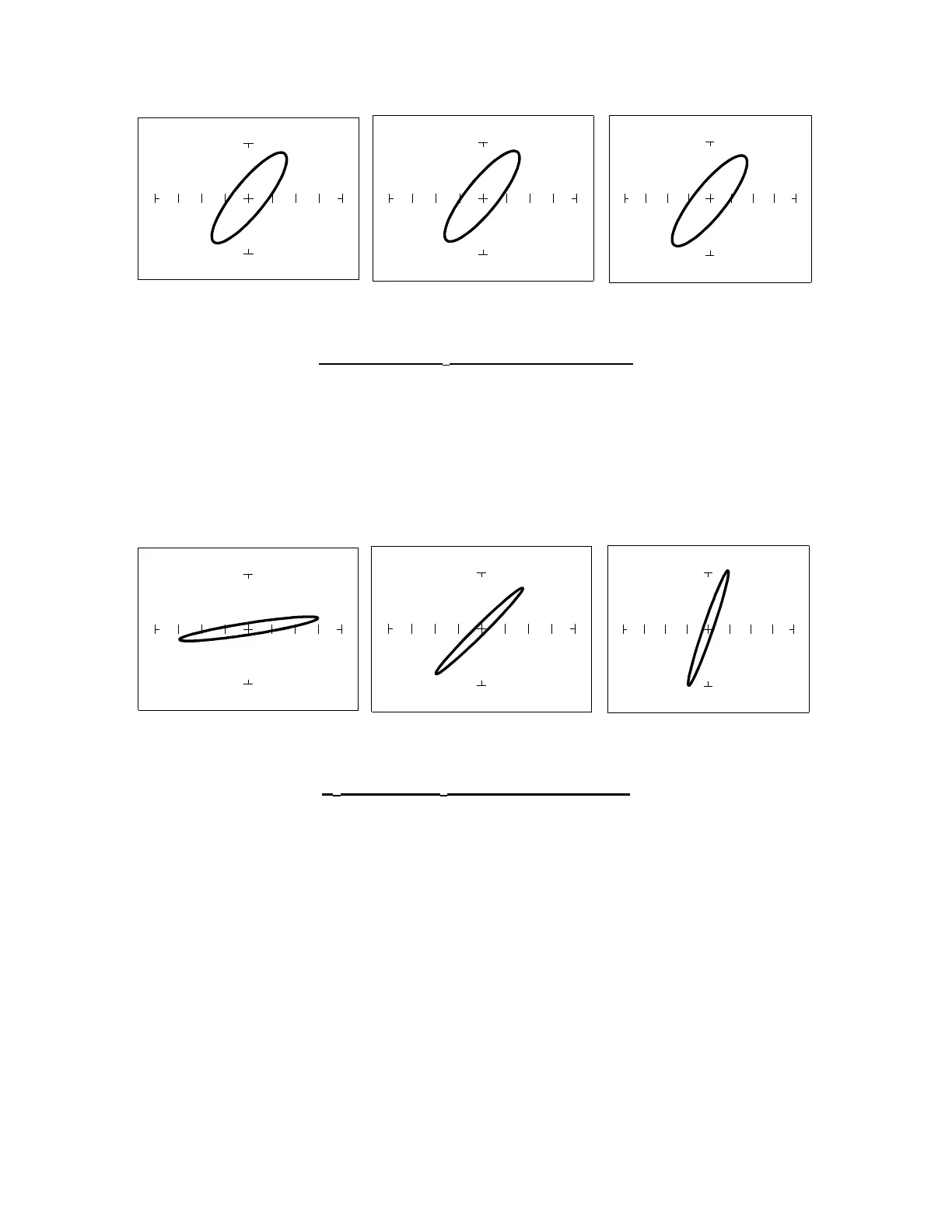
Effect of Voltage V
s
on Inductor Signatures
V
S
= 200 mV V
S
= 5 V V
S
= 10 V
100 Ω
ΩΩ
Ω Range, F
S
= 60 Hz, L = 12,000 µH
Figure 5-26. Effect of Varying V
S
on Inductor Signatures
Note that the signature does not change at the three test signal voltages. This means that the
inductor's resistance is not affected by changes in the test voltage.
Effect of Internal Resistance R
s
on Inductor Signatures
R
S
= 10 Ω
ΩΩ
Ω R
S
= 100 Ω
ΩΩ
Ω R
S
= 1kΩ
ΩΩ
Ω
V
S
= 200mV, F
S
= 60 Hz, L = 12,000 µH
Figure 5-27. Effect of Varying R
S
on Inductor Signatures
Note that the signature changes from a horizontal to a vertical position as the Tracker 2700's
internal resistance R
S
increases. This means the inductor's resistance can be analyzed by
matching it with the Tracker 2700's test signal resistance.
 Loading...