5-
28
Electromechanical Relays
A relay is a switch that's activated by an electrical control input. The relay consists of switch
contacts, magnets and an electromagnetic coil. The Tracker 2700 can test the coil part of the
relay by looking at its inductive Tracker signature. You can also connect the Tracker 2700’s DC
Source to the magnetic coil and while at the same time connecting the Tracker’s test signal to the
relay contacts to test the relay’s switching action directly.
Using the DC Source to Test a Reed Relay
Note that the maximum output voltage of the DC source is 5 Volts, so the relay coil must activate
at 5V or less. Refer to figure 5-33.
Do the following:
1. Select the 10V, 100Ω range.
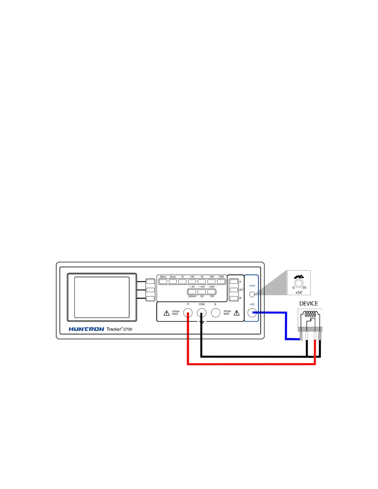
2. Connect the Tracker 2700 DC Source output +DC to the positive (+) lead of the relay coil.
3. Connect the Tracker 2700 COMMON to the relay's negative (-) lead).
4. Connect the black test lead from Tracker 2700’s COMMON terminal to the wiper side of the
relay switch contact.
5. Connect the red test lead from Tracker 2700’s TEST terminal to the other side of the relay
switch contact.
6. Rotate the DC level knob all the way counter-clockwise. Now rotate the knob slowly
clockwise and observe the relay contacts' signature. When a short circuit signature (vertical
line) is displayed, turn the DC level knob back and forth and watch the relay relay’s signature
change between an open and a short.
Figure 5-33. Tracker 2700 with Test Leads Connected to Relay's Coil
When applying Tracker 2700’s test signal to the coil, there may be an audible ringing sound
generated from the relay under test from the switch contacts being excited.
Review
 Loading...