6-
1
SECTION 6
TESTING DISCRETE SEMICONDUCTORS
6-1. Diodes
The most basic type of solid state semiconductor component is the diode. Diodes are formed by
creating a junction between p-type and n-type semiconductor material. The PN junction gives
diodes and semiconductor components polarity characteristics that allow them to conduct current
when an external voltage is applied. They conduct current in one direction, but not in the other.
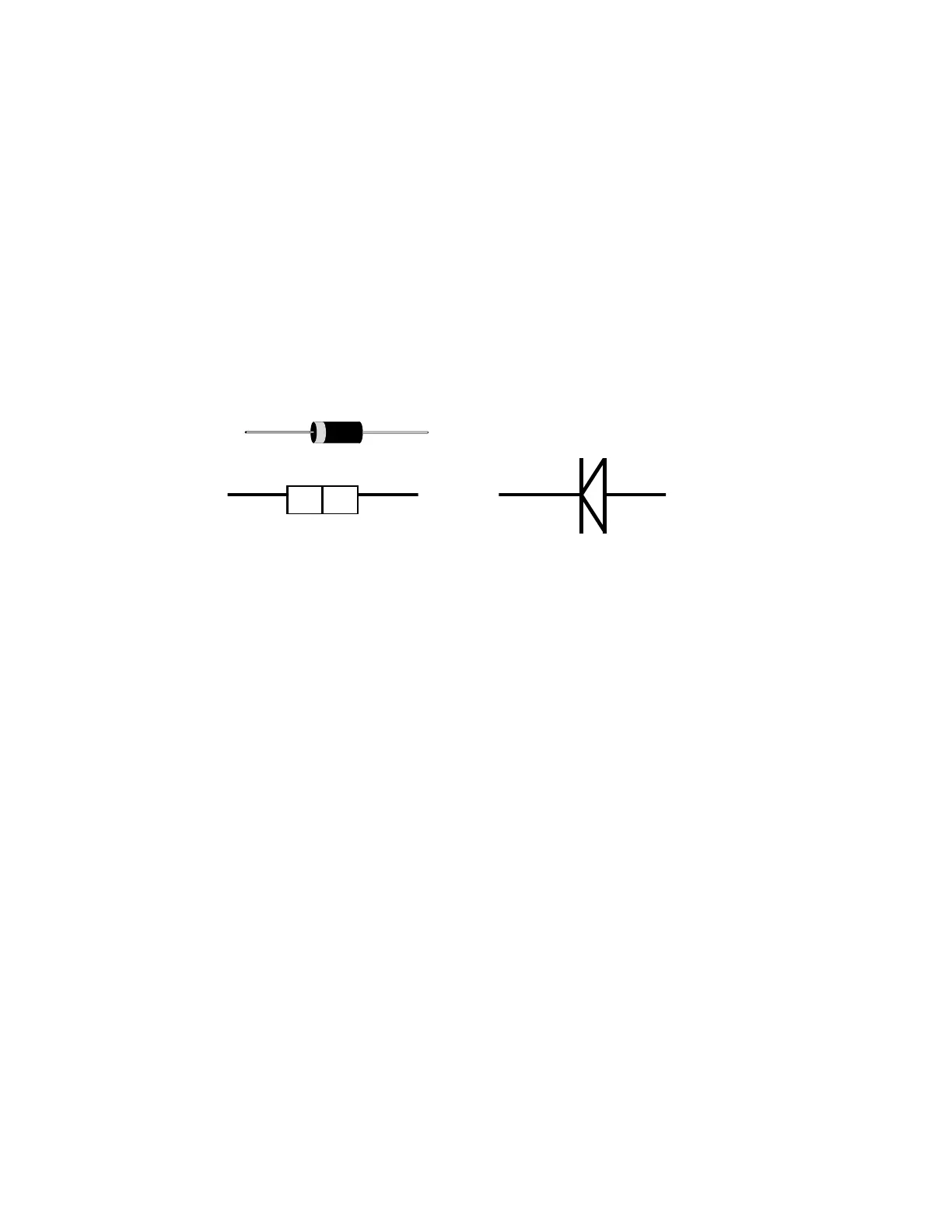
Current flows in a diode when the positive terminal (anode) is made more positive than the
negative terminal (cathode) by a predetermined value according to the specifications of the
device. Figure 6-1 shows how the diode symbol indicates the polarity of the diode.
C A T H O D E A N O D E
D IO D E S C H E M A T IC S Y M B O L
N P
+-
Figure 6-1. Diode and Schematic Symbol
DIODE TRACKER SIGNATURES
Diode signatures demonstrate the fundamental operation of a semiconductor junction. There is a
threshold or forward voltage V
F
(about 0.6V for a silicon diode) at which the diode begins to
conduct current. The diode acts as an open circuit and no current flows as long as the voltage
differential between the anode and cathode is below that threshold. As the anode to cathode
voltage becomes more positive, the diode will begin to conduct current. Once current begins to
flow in the diode, very small increases in anode voltage will cause very large increases in current.
In Tracker Signature Analysis, this is called the “knee” effect in which is the characteristic of a
good semiconductor junction.
 Loading...