6-
3
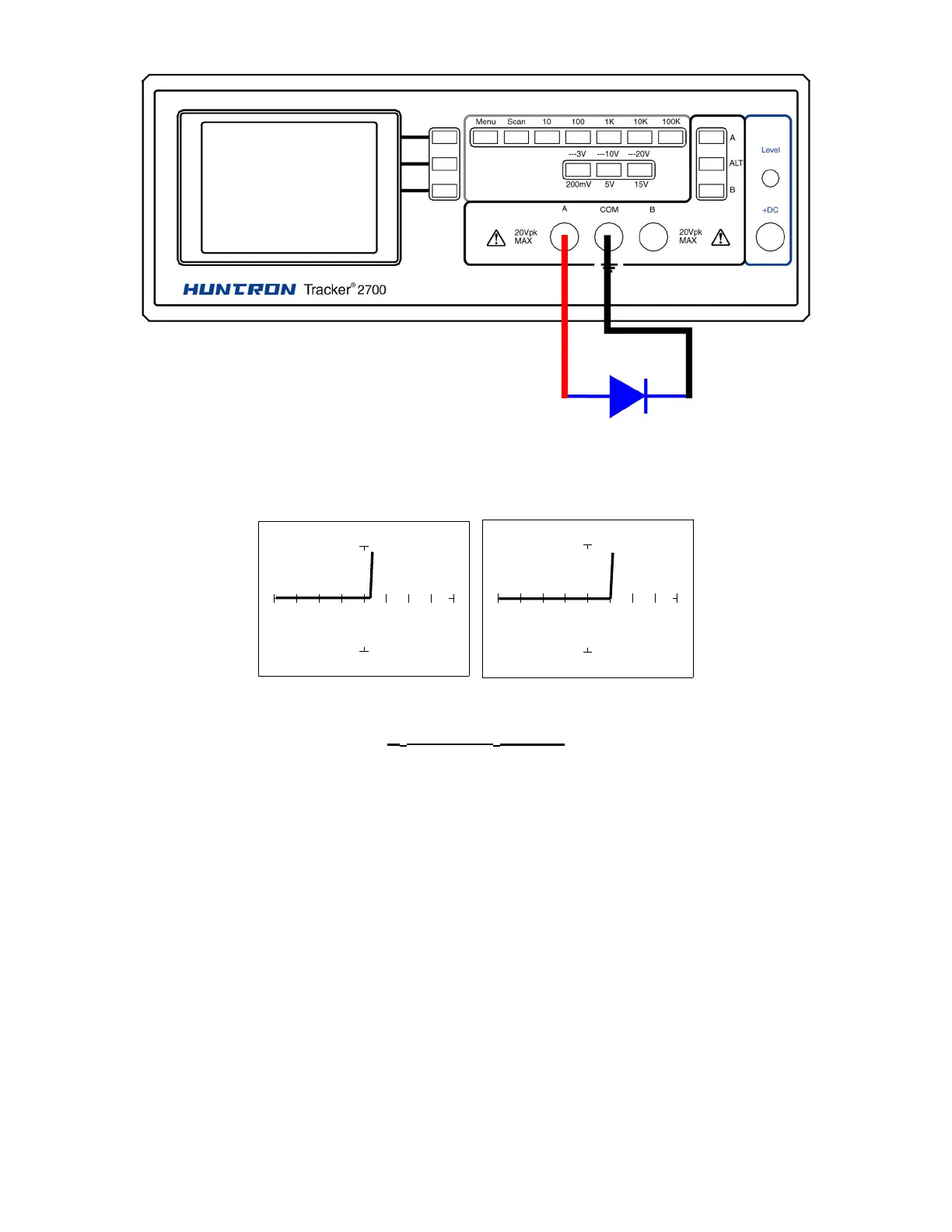
Figure 6-3. Tracker 2700 with Probes to a Diode
V
S
= 10 Volts V
S
= 3 Volts
R
S
= 100Ω
ΩΩ
Ω , F
S
= 60 Hz
Figure 6-4. Signature of a 1N914 Type Silicon Diode
The diode signatures shown above are similar. The test signal voltage for the signature on the
left is 10 V
P
. Each horizontal division on the display equals approximately 2.5 V. In this range
the diode's signature shows that its threshold or forward voltage is approximately 0.6 Volts. By
selecting the 3V test signal voltage, the 0.6 volt threshold is clearly visible for easier analysis.