6-
7
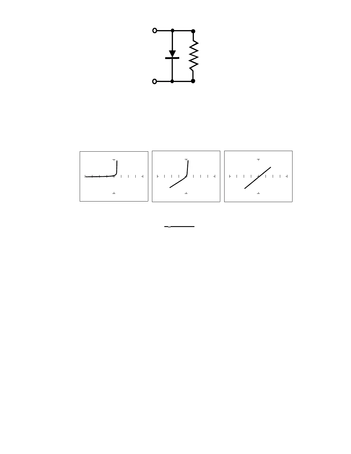
Figure 6-10. Composite Model of a Diode and Resistor in Parallel
V
S
= 10V, R
S
= 100Ω
ΩΩ
Ω V
S
=10 V, R
S
= 1 kΩ
ΩΩ
Ω V
S
=200 mV, R
S
= 1 kΩ
ΩΩ
Ω
F
S
= 60 Hz
Figure 6-11. Composite Signature - 1N914 Diode and 1.5 kΩ Resistor in Parallel
The signature on the left shows only the diode signature because the test signal resistance is set
below any visible contribution due to the 1.5 kΩ resistor. The composite signature in the center
consists of the distinctive slope of the resistor and the "knee" pattern of the diode. The signature
on the right shows only the resistor signature because the test signal voltage is below the diode's
threshold voltage. Again, when multiple components are connected together, it's important to
realize that the Tracker 2700 has the ability to selectively display the signature of a single
component.