6-
21
Darlington Bipolar Transistor Signatures
The Darlington transistor is basically two transistors paired together in a special configuration.
The emitter of the first transistor is connected to the base of the second transistor. The collectors
of both transistors are connected together. The base of the first transistor serves as the external
base lead and the emitter of the second transistor serves as the external emitter lead. A block
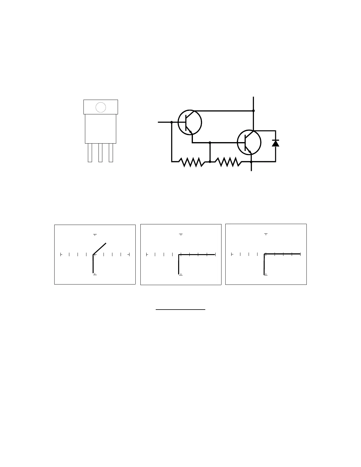
diagram of a darlington transistor and its Tracker signature are shown in the following figures.
Figure 6-29. Diagram of a Darlington Transistor
B-E Junction C-E Junction C-B Junction
15V, 10 kΩ
ΩΩ
Ω Range
Figure 6-30. Signature of a Darlington Transistor, TIP112 NPN Type.
Base to Common, Emitter to Common
Note that the B-E junction has a sloped leg bend in its signature caused by internal resistors R1
and R2.
B
C E
B