6-
22
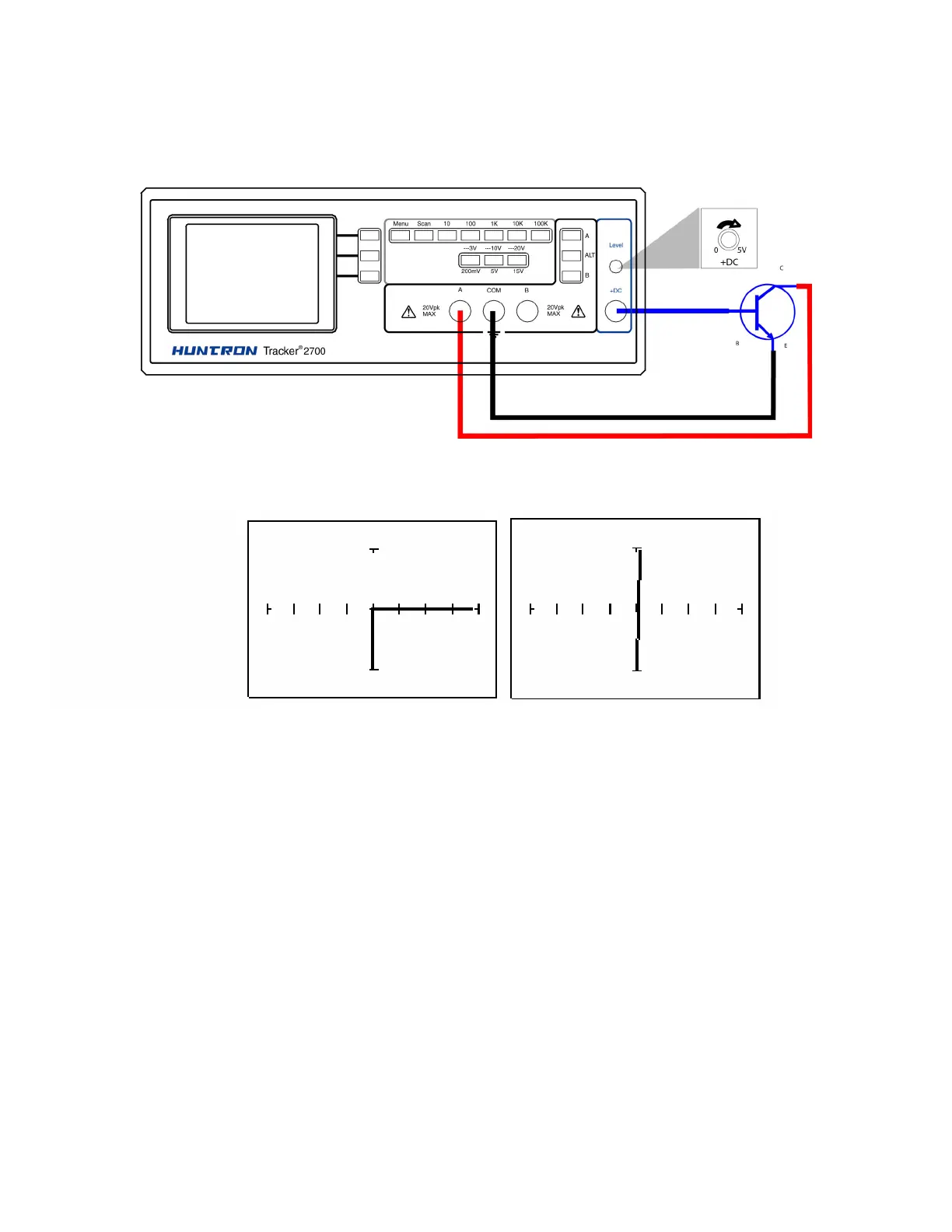
Using the DC Source to Test Transistor Operation
Figure 6-31a shows the test circuit for an NPN transistor using the DC Source to drive the base.
The constant current signature produced is similar to that produced by a transistor curve tracer
except that only one curve is shown instead of a family of curves. This technique can be useful
for functionally testing and matching transistor gain characteristics.
Figure 6-31a. DC Source Test Circuit for an NPN Transistor
DC level = 0V DC Level = 5V
Figure 6-31b. Signatures for Test Circuit with an NPN Transistor